Home › Engine / Hybrid System › HYBRID / BATTERY CONTROL › HYBRID CONTROL SYSTEM › from 2016.05
RM2070E _51 Engine / Hybrid System _061906 HYBRID / BATTERY CONTROL _0301573 HYBRID CONTROL SYSTEM C

HYBRID / BATTERY CONTROL  HYBRID CONTROL SYSTEM  P0617-142  Starter Relay Circuit High  


DESCRIPTION

DTC No. INF Code DTC Detection Condition Trouble Area
P0617 142 An ST signal from the hybrid vehicle control ECU assembly is on when the power switch is off.
(2 trip detection logic)
·

Wire harness or connector

·

Hybrid vehicle control ECU

·

Certification ECU (smart key ECU assembly)


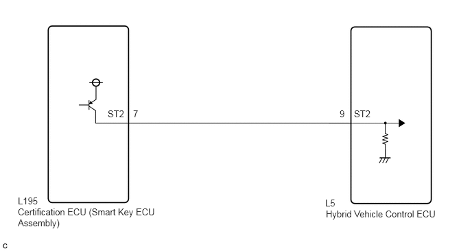
WIRING DIAGRAM

A148900E26
1.635,1.646 1.969,1.823 0.333,0.177 10 false ST2 5.375,1.646 5.708,1.823 0.333,0.177 10 false ST2 5.156,1.646 5.302,1.833 0.146,0.188 10 false 9 2.021,1.646 2.292,1.833 0.271,0.188 10 false 7 0.271,3.135 2.438,3.594 2.167,0.458 10 false Certification ECU (Smart Key ECU Assembly) 0.271,2.969 0.635,3.167 0.365,0.198 10 false L195 4.948,3.167 6.76,3.375 1.813,0.208 10 false Hybrid Vehicle Control ECU 4.938,3 5.302,3.198 0.365,0.198 10 false L5

CAUTION / NOTICE / HINT

NOTICE:

Before replacing the certification ECU (smart key ECU assembly), refer to Service Bulletin.


HINT:

After the repair, clear the DTCs and perform the following procedure to check that DTCs are not output.

1.

Turn the power switch off and wait for 5 seconds or more.


PROCEDURE

1.CHECK CONNECTOR CONNECTION CONDITION (HYBRID VEHICLE CONTROL ECU CONNECTOR)

OK

2.CHECK CONNECTOR CONNECTION CONDITION (CERTIFICATION ECU (SMART KEY ECU ASSEMBLY))

NG

CONNECT SECURELY

2.CHECK CONNECTOR CONNECTION CONDITION (CERTIFICATION ECU (SMART KEY ECU ASSEMBLY))
a.

Check the connector connection condition of the certification ECU (smart key ECU assembly).

HINT:

Refer to the Service Bulletin for the installation position.


OK:

The connector is connected securely and there are no contact problems.


OK

3.CHECK HARNESS AND CONNECTOR (ST2 TERMINAL VOLTAGE)

NG

CONNECT SECURELY

3.CHECK HARNESS AND CONNECTOR (ST2 TERMINAL VOLTAGE)
a.

Turn the power switch off.


b.
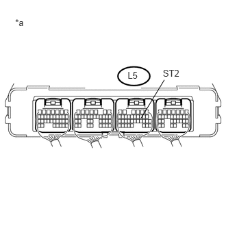
U190709E01
2.477,1.032 2.795,1.225 0.318,0.193 10 ST2 2.148,1.793 2.499,1.215 false 0.231,0.264 0.477,0.500 0.246,0.236 10 *a 1.941,1.063 2.318,1.225 0.377,0.163 10 L5

Measure the voltage according to the value(s) in the table below.

Standard Voltage:
Tester Connection Switch Condition Specified Condition
L5-9 (ST2) - Body ground Power switch off Below 1 V


Text in Illustration
*a Component with harness connected
(Hybrid Vehicle Control ECU)


OK

NG

4.CHECK HARNESS AND CONNECTOR (HYBRID VEHICLE CONTROL ECU - CERTIFICATION ECU (SMART KEY ECU ASSEMBLY))
a.

Disconnect the L195 certification ECU (smart key ECU assembly) connector.


b.
U190709E01
2.477,1.032 2.795,1.225 0.318,0.193 10 ST2 2.148,1.793 2.499,1.215 false 0.231,0.264 0.477,0.500 0.246,0.236 10 *a 1.941,1.063 2.318,1.225 0.377,0.163 10 L5

Measure the voltage according to the value(s) in the table below.

Standard Voltage:
Tester Connection Switch Condition Specified Condition
L5-9 (ST2) - Body ground Power switch off Below 1 V


Text in Illustration
*a Component with harness connected
(Hybrid Vehicle Control ECU)


c.

Reconnect the L195 certification ECU (smart key ECU assembly) connector.


OK

REPLACE CERTIFICATION ECU (SMART KEY ECU ASSEMBLY)

NG

REPAIR OR REPLACE HARNESS OR CONNECTOR