HYBRID / BATTERY CONTROL HV BATTERY INSPECTION
PROCEDURE

 G9510
1.INSPECT HV BATTERY
Remove the HV battery from the vehicle (See page Engine / Hybrid System>HYBRID / BATTERY CONTROL>HV BATTERY>REMOVAL).
Remove the No. 2 hybrid vehicle battery cover panel LH from the HV battery (See page Engine / Hybrid System>HYBRID / BATTERY CONTROL>HV BATTERY>REMOVAL).
Remove the No. 2 hybrid battery shield sub-assembly from the HV battery (See page Engine / Hybrid System>HYBRID / BATTERY CONTROL>HV BATTERY>REMOVAL).
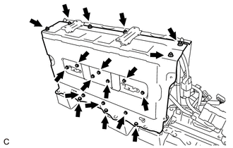
Remove the 6 nuts, 13 bolts and hybrid vehicle battery cover sub-assembly RH from the HV battery.
- CAUTION:
-
Be sure to wear insulated gloves and protective goggles.
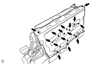
Remove the 2 nuts, 13 bolts and hybrid vehicle battery cover sub-assembly LH from the HV battery.
- CAUTION:
-
Be sure to wear insulated gloves and protective goggles.
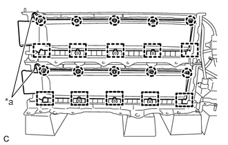
Disengage the 10 claws and 10 guides to remove the 2 No. 1 hybrid vehicle battery cover ducts from the HV battery.
| *a | Inlet Air Temperature Sensor |
- CAUTION:
-
Be sure to wear insulated gloves and protective goggles.
- NOTICE:
- ·
Do not disconnect the inlet air temperature sensor from the No. 1 hybrid vehicle battery cover duct.
·Do not apply excessive force to the inlet air temperature sensor wire harness when removing the No. 1 hybrid vehicle battery cover duct.
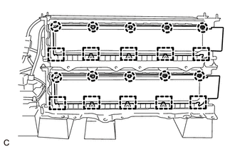
Disengage the 10 claws and 10 guides to remove the 2 hybrid vehicle battery cover exhaust ducts from the HV battery.
- CAUTION:
-
Be sure to wear insulated gloves and protective goggles.
Inspect HV battery:
- CAUTION:
-
Be sure to wear insulated gloves and protective goggles.
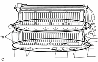
Check that no electrolyte is leaking from each HV battery stack.
| *a | Check Part |
- OK:
There is no electrolyte leaking from the HV battery stacks.
If the result is not as specified, replace the HV battery.
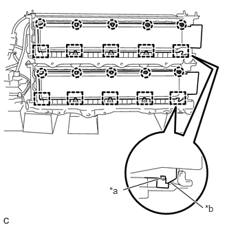
Align the protrusion of each hybrid vehicle battery cover exhaust duct with each guide (A).
| *a | Guide (A) |
| *b | Protrusion |
- CAUTION:
-
Be sure to wear insulated gloves and protective goggles.
Engage the 10 guides and 10 claws to install the 2 hybrid vehicle battery cover exhaust ducts to the HV battery.
- CAUTION:
-
Be sure to wear insulated gloves and protective goggles.
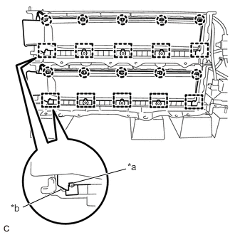
Align the protrusion of each No. 1 hybrid vehicle battery cover duct with each guide (A).
| *a | Guide (A) |
| *b | Protrusion |
- CAUTION:
-
Be sure to wear insulated gloves and protective goggles.
Engage the 10 guides and 10 claws to install the 2 No. 1 hybrid vehicle battery cover ducts to the HV battery.
- CAUTION:
-
Be sure to wear insulated gloves and protective goggles.
- NOTICE:
-
Do not apply excessive force to the inlet air temperature sensor wire harness when installing the No. 1 hybrid vehicle battery cover duct.
Install the hybrid vehicle battery cover sub-assembly LH to the HV battery with the 2 nuts and 13 bolts.
- Torque:
- 7.5 N*m (76 kgf*cm, 66 in.*lbf)
- CAUTION:
-
Be sure to wear insulated gloves and protective goggles.
Install the hybrid vehicle battery cover sub-assembly RH to the HV battery with the 6 nuts and 13 bolts.
- Torque:
- 7.5 N*m (76 kgf*cm, 66 in.*lbf)
- CAUTION:
-
Be sure to wear insulated gloves and protective goggles.
Inspect inlet air temperature sensor:
- CAUTION:
-
Wear insulated gloves.
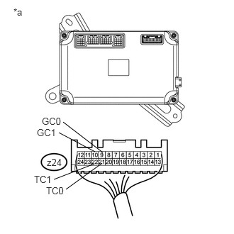
Measure the resistance according to the value(s) in the table below.
- Standard Resistance:
Tester Connection Thermistor Temperature Specified Condition z24-21 (TC0) - z24-9 (GC0) 0°C (32°F) 26.7 to 27.8 kΩ 25°C (77°F) 9.9 to 10.1 kΩ 40°C (104°F) 5.73 to 5.92 kΩ z24-22 (TC1) - z24-10 (GC1) 0°C (32°F) () 26.7 to 27.8 kΩ 25°C (77°F) 9.9 to 10.1 kΩ 40°C (104°F) 5.73 to 5.92 kΩ
Text in Illustration *a Rear view of wire harness connector
(to Battery Smart Unit)
If the result is not as specified, replace the HV battery.
Install the No. 2 hybrid battery shield sub-assembly to the HV battery (See page Engine / Hybrid System>HYBRID / BATTERY CONTROL>HV BATTERY>INSTALLATION).
Install the No. 2 hybrid vehicle battery cover panel LH to the HV battery (See page Engine / Hybrid System>HYBRID / BATTERY CONTROL>HV BATTERY>INSTALLATION).
Install the HV battery to the vehicle (See page Engine / Hybrid System>HYBRID / BATTERY CONTROL>HV BATTERY>INSTALLATION).