2ZR-FXE ENGINE MECHANICAL REAR CRANKSHAFT OIL SEAL INSTALLATION
PROCEDURE

 11401L
1.INSTALL REAR ENGINE OIL SEAL
Apply MP grease to the lip of a new oil seal.
- NOTICE:
-
Keep the lip free from foreign matter.
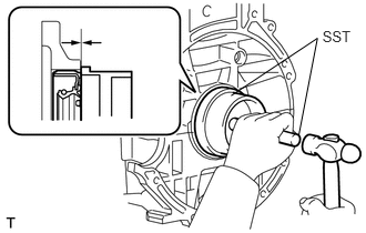
Using SST and a hammer, tap in the oil seal until its surface is flush with the rear oil seal retainer edge.
- SST
- 09223-15030
09950-70010 (09951-07100)
- NOTICE:
- ·
Wipe any extra grease off the crankshaft.
·Do not tap the oil seal at an angle.
13405
2.INSTALL FLYWHEEL SUB-ASSEMBLY
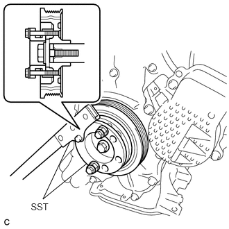
Using SST, hold the crankshaft.
- SST
- 09213-58014 (91551-80840)
09330-00021
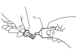
Apply adhesive to the 2 or 3 end threads of the bolts.
| *1 | Adhesive |
- Adhesive:
Toyota Genuine Adhesive 1324, Three Bond 1324 or equivalent
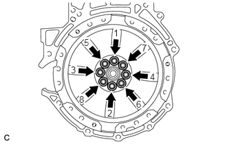
Using several steps, uniformly install and tighten the 8 bolts in the sequence shown in the illustration.
- Torque:
- 49 N*m (500 kgf*cm, 36 ft.*lbf)
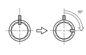
Mark the front of the bolts with paint.

|
Paint Mark |
Retighten the 8 bolts 90° in the same sequence.
Check that the paint marks are now at a 90° angle to the front.
Check that the crankshaft turns smoothly.
31270
3.INSTALL TRANSMISSION INPUT DAMPER ASSEMBLY
Using SST, hold the crankshaft.
- SST
- 09213-58014 (91551-80840)
09330-00021
Install the transmission input damper.
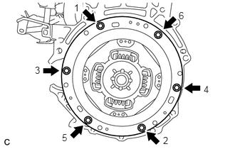
In several steps, uniformly install and tighten the 6 bolts in the sequence shown in the illustration.
- Torque:
- 30 N*m (306 kgf*cm, 22 ft.*lbf)
- NOTICE:
-
Take care not to insert the transmission input damper in a wrong direction.
30900
4.INSTALL HYBRID VEHICLE TRANSAXLE ASSEMBLY
Install the hybrid vehicle transaxle assembly (See page Drivetrain>P410 (HYBRID TRANSMISSION / TRANSAXLE)>HYBRID VEHICLE TRANSAXLE>INSTALLATION).
- NOTICE:
-
Be careful not to apply excess force to the transmission input damper assembly when removing or installing the hybrid vehicle transaxle assembly. If excess force is applied, the transmission input damper assembly may be damaged, or its splines may become misaligned.