CRUISE CONTROL DYNAMIC RADAR CRUISE CONTROL SYSTEM C1A4A Skid Control Buzzer Circuit
DESCRIPTION
A buzzer sounds to alert the driver when the vehicle-to-vehicle distance becomes less than the set value.
| DTC No. | DTC Detection Condition | Trouble Area |
|---|---|---|
| C1A4A | When the power switch is on (IG), a skid control buzzer assembly circuit malfunction signal is received from the millimeter wave radar sensor assembly for 3 seconds or more while the vehicle is being driven at a speed of 36 km/h (22 mph) or more. | ·
Skid control buzzer assembly ·
Skid control buzzer circuit ·
Millimeter wave radar sensor assembly ·
Driving support ECU assembly |
WIRING DIAGRAM
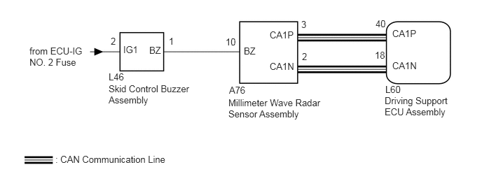
PROCEDURE
Connect the GTS to the DLC3.
Turn the power switch on (IG).
Turn the GTS on.
Enter the following menus: Body Electrical / Pre-Crash 2 / Active Test.
Perform Active Test according to the display on the GTS.
| Tester Display | Test Part | Control Range | Diagnostic Note |
|---|---|---|---|
| Radar Cruise Approach Alarm Buzzer | Skid control buzzer assembly | ON or OFF | Buzzer can be heard |
- Result:
Result Proceed to Skid control buzzer assembly does not sound A Skid control buzzer assembly sounds B
A
B
Remove the skid control buzzer assembly (See page Vehicle Interior>PRE-CRASH SAFETY>PRE-CRASH SAFETY SYSTEM WARNING BUZZER>REMOVAL).
Inspect the skid control buzzer assembly (See page Vehicle Interior>PRE-CRASH SAFETY>PRE-CRASH SAFETY SYSTEM WARNING BUZZER>INSPECTION).
OK
NG
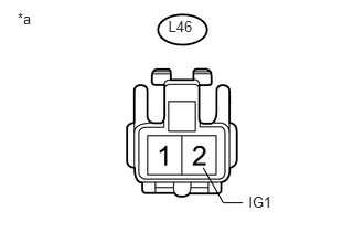
Disconnect the skid control buzzer assembly connector.
Measure the voltage according to the value(s) in the table below.
- Standard Voltage:
Tester Connection Condition Specified Condition L46-2 (IG1) - Body ground Power switch on (IG) 11 to 14 V L46-2 (IG1) - Body ground Power switch off Below 1 V
Text in Illustration *a Front view of wire harness connector
(to Skid Control Buzzer Assembly)
Connect the skid control buzzer assembly connector.
OK
NG
Disconnect the skid control buzzer assembly connector.
Disconnect the millimeter wave radar sensor assembly connector.
Measure the resistance according to the value(s) in the table below.
- Standard Resistance:
Tester Connection Condition Specified Condition L46-1 (BZ) - A76-10 (BZ) Always Below 1 Ω L46-1 (BZ) or A76-10 (BZ) - Body ground Always 10 kΩ or higher
Connect the skid control buzzer assembly connector.
Connect the millimeter wave radar sensor assembly connector.
OK
NG
Replace the millimeter wave radar sensor assembly (See page Engine / Hybrid System>CRUISE CONTROL>MILLIMETER WAVE RADAR SENSOR>REMOVAL).
Adjust the millimeter wave radar sensor assembly (See page Engine / Hybrid System>CRUISE CONTROL>MILLIMETER WAVE RADAR SENSOR>ADJUSTMENT)
NEXT
Connect the GTS to the DLC3.
Turn the power switch on (IG).
Turn the GTS on.
Clear the DTCs (See page Engine / Hybrid System>CRUISE CONTROL>DYNAMIC RADAR CRUISE CONTROL SYSTEM>DTC CHECK / CLEAR).
Perform the following to make sure that the DTC detection conditions are met.
- HINT:
-
If the detection conditions are not met, the malfunction cannot be detected.
Drive the vehicle at a speed of between approximately 50 km/h (30 mph) and 170 km/h (105 mph).
Turn the cruise control system on using the cruise control switch (ON-OFF button).
Push the cruise control switch to -/SET to begin control of vehicle speed using the cruise control system.
Enter the following menus: Powertrain / Radar Cruise / Trouble Codes.
Check for DTCs.
- Result:
Result Proceed to DTC is not output A DTC C1A4A is output B
A
B