Home › Drivetrain › P410 (HYBRID TRANSMISSION / TRANSAXLE) › ELECTRONIC SHIFT LEVER SYSTEM › from 2016.05
RM2070E _52 Drivetrain _061915 P410 HYBRID TRANSMISSION / TRANSAXLE _0301645 ELECTRONIC SHIFT LEVER SYSTEM C

P410 HYBRID TRANSMISSION / TRANSAXLE  ELECTRONIC SHIFT LEVER SYSTEM  C2307  Power Supply  


DESCRIPTION

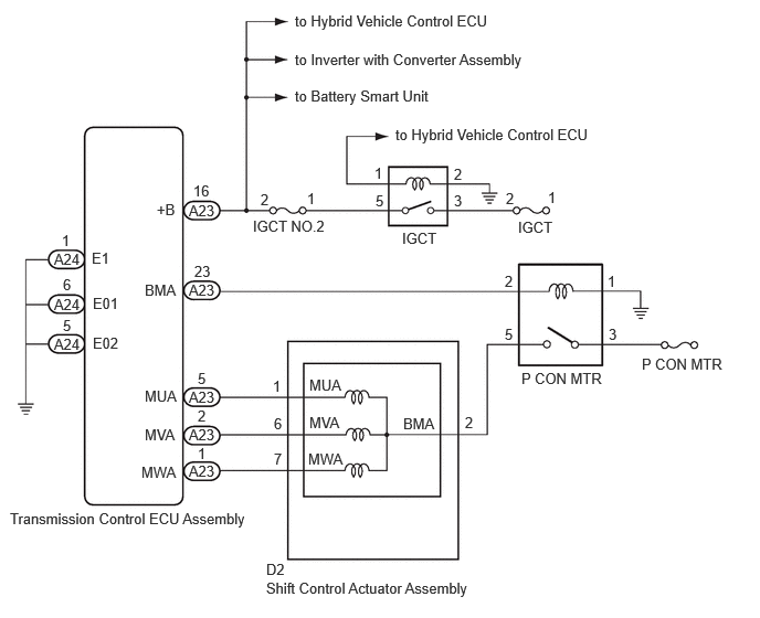
The shift control actuator assembly consists of a parking lock motor and rotation angle sensor. The transmission control ECU assembly receives a P position switch signal from the hybrid vehicle control ECU and activates the parking lock motor by controlling current, causing the parking lock mechanism to switch. The transmission control ECU assembly stores this DTC when it detects a malfunction in the parking lock motor system and/or the ground circuit.

DTC No. DTC Detection Condition Trouble Area
C2307 With the power switch on (IG) (IG circuit malfunction is not detected), current of the parking lock motor is 50 A or more or there is an open in the transmission control ECU assembly terminal E1 circuit for 0.1 seconds or more.
·

Transmission control ECU assembly

·

Wire harness or connector


WIRING DIAGRAM

C481598E05
3.729,1.188 6.469,1.396 2.74,0.208 10 false to Hybrid Vehicle Control ECU 4.885,2.063 5.781,2.385 0.896,0.323 10 false IGCT 3.792,2.167 4.688,2.49 0.896,0.323 10 false IGCT 2.385,2.052 3.281,2.375 0.896,0.323 10 false IGCT NO.2 6.052,3.354 6.948,3.677 0.896,0.323 10 false P CON MTR 4.917,3.49 5.813,3.813 0.896,0.323 10 false P CON MTR 2.51,5.469 4.667,5.76 2.156,0.292 10 false Shift Control Actuator Assembly 0.094,4.813 2.438,5.219 2.344,0.406 10 false Transmission Control ECU Assembly 5.167,1.781 5.385,2.021 0.219,0.24 10 false 1 4.771,1.792 4.99,2.031 0.219,0.24 10 false 2 4.281,1.563 4.5,1.802 0.219,0.24 10 false 2 3.531,1.552 3.75,1.792 0.219,0.24 10 false 1 4.281,1.813 4.5,2.052 0.219,0.24 10 false 3 3.542,1.813 3.76,2.052 0.219,0.24 10 false 5 2.896,1.792 3.115,2.031 0.219,0.24 10 false 1 2.458,1.802 2.677,2.042 0.219,0.24 10 false 2 5.729,2.573 5.948,2.813 0.219,0.24 10 false 1 4.76,2.573 4.979,2.813 0.219,0.24 10 false 2 4.76,3.073 4.979,3.313 0.219,0.24 10 false 5 5.74,3.073 5.979,3.292 0.24,0.219 10 false 3 4.385,3.906 4.604,4.146 0.219,0.24 10 false 2 2.573,3.563 2.792,3.802 0.219,0.24 10 false 1 2.583,3.917 2.802,4.156 0.219,0.24 10 false 6 2.583,4.25 2.802,4.49 0.219,0.24 10 false 7 3.802,3.917 4.24,4.271 0.438,0.354 10 false BMA 1.365,2.656 1.802,3.01 0.438,0.354 10 false BMA 2.917,3.552 3.354,3.906 0.438,0.354 10 false MUA 2.917,3.906 3.354,4.26 0.438,0.354 10 false MVA 2.906,4.25 3.344,4.604 0.438,0.354 10 false MWA 1.365,3.656 1.802,4.01 0.438,0.354 10 false MUA 1.365,4.021 1.802,4.375 0.438,0.354 10 false MVA 1.333,4.375 1.771,4.729 0.438,0.354 10 false MWA 0.51,2.365 0.833,2.583 0.323,0.219 10 false A24 1.823,1.719 2.083,1.958 0.26,0.24 10 false 16 1.833,2.479 2.094,2.719 0.26,0.24 10 false 23 1.865,3.49 2.125,3.729 0.26,0.24 10 false 5 1.865,3.844 2.083,4.083 0.219,0.24 10 false 2 1.865,4.198 2.083,4.438 0.219,0.24 10 false 1 0.594,2.604 0.813,2.844 0.219,0.24 10 false 6 0.583,2.188 0.802,2.427 0.219,0.24 10 false 1 0.594,2.99 0.813,3.229 0.219,0.24 10 false 5 0.865,2.354 1.135,2.594 0.271,0.24 10 false E1 1.479,1.896 1.75,2.135 0.271,0.24 10 false +B 0.875,2.781 1.281,3.021 0.406,0.24 10 false E01 0.875,3.156 1.281,3.396 0.406,0.24 10 false E02 2.51,5.292 2.833,5.51 0.323,0.219 10 false D2 0.51,2.792 0.833,3.01 0.323,0.219 10 false A24 0.51,3.167 0.833,3.385 0.323,0.219 10 false A24 1.781,1.906 2.104,2.125 0.323,0.219 10 false A23 1.781,2.656 2.104,2.875 0.323,0.219 10 false A23 1.781,3.667 2.104,3.885 0.323,0.219 10 false A23 1.781,4.021 2.104,4.24 0.323,0.219 10 false A23 1.781,4.365 2.104,4.583 0.323,0.219 10 false A23 2.781,0.115 5.521,0.323 2.74,0.208 10 false to Hybrid Vehicle Control ECU 2.781,0.479 5.521,0.688 2.74,0.208 10 false to Inverter with Converter Assembly 2.781,0.823 5.521,1.031 2.74,0.208 10 false to Battery Smart Unit

CAUTION / NOTICE / HINT

NOTICE:

It may not be possible to clear the following DTCs using the GTS: DTC C2300 (Actuator System Malfunction), C2301 (Shift Changing Time Malfunction), C2303 (Short in Power Source Relay Circuit), C2304 (Open or Short Circuit in U Phase), C2305 (Open or Short Circuit in V Phase), C2306 (Open or Short Circuit in W Phase), C2307 (Power Supply) and C2309 (Open in B+ Circuit). In such cases, disconnect the P CON MAIN fuse and wait for at least 60 seconds to clear the DTCs after the repair.


PROCEDURE

1.CHECK HARNESS AND CONNECTOR (TRANSMISSION CONTROL ECU ASSEMBLY - BODY GROUND)
a.

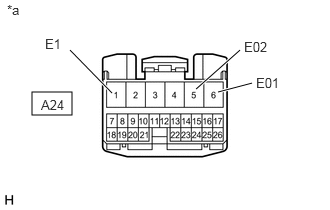
Disconnect the A24 transmission control ECU assembly connector.

b.
C208987E21
0.333,0.958 0.75,1.198 0.417,0.24 2.042,0.927 2.5,0.521 true 2.271,0.958 2.625,0.865 true 1.167,0.969 0.729,0.521 true 2.667,0.781 3.031,1.083 0.365,0.302 10 false E01 0.073,0.021 0.25,0.198 0.177,0.177 10 false *a 0.427,1.01 0.719,1.271 0.292,0.26 10 false A24 2.542,0.406 2.885,0.615 0.344,0.208 10 false E02 0.469,0.375 0.833,0.677 0.365,0.302 10 false E1

Measure the resistance according to the value(s) in the table below.

Standard Resistance (Check for Open):
Tester Connection Condition Specified Condition
A24-1 (E1) - Body ground Power switch off Below 1 Ω
A24-6 (E01) - Body ground Power switch off Below 1 Ω
A24-5 (E02) - Body ground Power switch off Below 1 Ω


Text in Illustration
*a Front view of wire harness connector
(to Transmission Control ECU Assembly)


c.

Connect the A24 transmission control ECU assembly connector.


OK

2.CHECK HARNESS AND CONNECTOR (TRANSMISSION CONTROL ECU ASSEMBLY - SHIFT CONTROL ACTUATOR ASSEMBLY)

NG

REPAIR OR REPLACE HARNESS OR CONNECTOR

2.CHECK HARNESS AND CONNECTOR (TRANSMISSION CONTROL ECU ASSEMBLY - SHIFT CONTROL ACTUATOR ASSEMBLY)

OK

REPLACE TRANSMISSION CONTROL ECU ASSEMBLY

NG

REPAIR OR REPLACE HARNESS OR CONNECTOR