Home › Steering › POWER ASSIST SYSTEMS › POWER STEERING SYSTEM › 2012.03–2014.11
RM2070E _55 Steering _061928 POWER ASSIST SYSTEMS _0301712 POWER STEERING SYSTEM J

POWER ASSIST SYSTEMS  POWER STEERING SYSTEM  TS and CG Terminal Circuit  


DESCRIPTION

Assist map writing can be performed after entering Signal Check by connecting the TS and CG terminal of the DLC3 using SST (See page Steering>POWER ASSIST SYSTEMS>POWER STEERING SYSTEM>CALIBRATION).

WIRING DIAGRAM
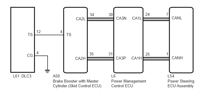
C264871E01
1.263,1.024 1.438,1.184 0.174,0.161 10 12 0.964,1.122 1.166,1.282 0.202,0.161 10 TS 2.091,1.024 2.191,1.184 0.100,0.161 10 4 3.119,0.425 3.296,0.585 0.176,0.161 10 34 2.638,0.57 3.028,0.730 0.390,0.161 10 CA2L 3.107,1.805 3.292,1.966 0.185,0.161 10 35 2.615,1.962 3.028,2.122 0.412,0.161 10 CA2H 5.971,0.542 6.360,0.702 0.390,0.161 10 CANL 5.78,0.416 5.875,0.576 0.095,0.161 10 7 5.78,1.807 5.875,1.968 0.095,0.161 10 1 5.971,1.934 6.383,2.094 0.412,0.161 10 CANH 1.263,1.758 1.438,1.918 0.174,0.161 10 4 0.938,1.856 1.166,2.016 0.228,0.161 10 CG 0.45,2.576 0.704,2.737 0.254,0.161 10 L61 0.744,2.576 1.120,2.737 0.375,0.161 10 DLC3 3.87,2.745 5.138,3.075 1.269,0.330 10 Power Management Control ECU 5.831,2.745 6.799,3.075 0.968,0.330 10 Power Steering ECU Assembly 5.831,2.577 6.089,2.759 0.259,0.181 10 L54 2.306,1.122 2.514,1.282 0.209,0.161 10 TS 4.593,0.556 4.982,0.716 0.390,0.161 10 CA1L 4.57,1.948 4.982,2.108 0.412,0.161 10 CA1H 4.037,0.556 4.426,0.716 0.390,0.161 10 CA3N 4.028,1.948 4.440,2.108 0.412,0.161 10 CA3P 1.838,2.745 3.600,3.087 1.762,0.341 10 Brake Booster with Master Cylinder (Skid Control ECU) 3.87,2.577 4.234,2.738 0.365,0.161 10 L6 1.838,2.577 2.203,2.738 0.365,0.161 10 A58 3.776,0.425 3.952,0.585 0.176,0.161 10 30 3.772,1.805 3.958,1.966 0.185,0.161 10 31 5.055,0.415 5.231,0.576 0.176,0.161 10 24 5.06,1.812 5.236,1.972 0.176,0.161 10 25

CAUTION / NOTICE / HINT

NOTICE:

If the power steering ECU assembly has been replaced with a new one, perform assist map writing and rotation angle sensor value initialization torque sensor zero point calibration after performing the initialization of the torque sensor zero point value (See page Steering>POWER ASSIST SYSTEMS>POWER STEERING SYSTEM>CALIBRATION).


PROCEDURE

1.CHECK CAN COMMUNICATION SYSTEM
a.

Check if a CAN communication system DTC is output (See page Power Source / Network>NETWORKING>CAN COMMUNICATION SYSTEM (w/o Central Gateway ECU)>DIAGNOSIS SYSTEM).

Result:
Result Proceed to
DTC is not output A
DTC is output B


OK

2.CHECK HARNESS AND CONNECTOR (SKID CONTROL ECU - TS of DLC3)

NG

2.CHECK HARNESS AND CONNECTOR (SKID CONTROL ECU - TS of DLC3)
a.

Disconnect the skid control ECU connector.


b.

Measure the resistance according to the value(s) in the table below.

Standard Resistance:
Tester Connection Condition Specified Condition
A58-4 (TS) - L61-12 (TS) Always Below 1 Ω
A58-4 (TS) - Body ground Always 10 kΩ or higher


OK

3.CHECK HARNESS AND CONNECTOR (CG of DLC3 - BODY GROUND)

NG

REPAIR OR REPLACE HARNESS OR CONNECTOR

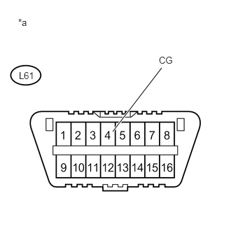
3.CHECK HARNESS AND CONNECTOR (CG of DLC3 - BODY GROUND)
a.
U191005E02
1.677,1.958 2.406,1.01 true 0.271,0.25 0.458,0.417 0.188,0.167 10 false *a 2.365,0.813 2.604,0.979 0.24,0.167 10 false CG 0.281,1.042 0.531,1.188 0.25,0.146 10 false L61

Measure the resistance according to the value(s) in the table below.

Standard Resistance:
Tester Connection Condition Specified Condition
L61-4 (CG) - Body ground Always Below 1 Ω


Text in Illustration
*a Front view of DLC3


HINT:

If troubleshooting has been carried out according to Problem Symptoms Table, refer back to the table and proceed to the next step before replacing the part (See page Steering>POWER ASSIST SYSTEMS>POWER STEERING SYSTEM>PROBLEM SYMPTOMS TABLE).


OK

REPLACE POWER STEERING ECU ASSEMBLY

NG

REPAIR OR REPLACE HARNESS OR CONNECTOR