Home › Vehicle Interior › THEFT DETERRENT / KEYLESS ENTRY › THEFT DETERRENT SYSTEM › 2012.03–2020.08
RM2070E _58 Vehicle Interior _061938 THEFT DETERRENT / KEYLESS ENTRY _0301770 THEFT DETERRENT SYSTEM J

THEFT DETERRENT / KEYLESS ENTRY  THEFT DETERRENT SYSTEM  Theft Warning Siren Circuit  


DESCRIPTION

The theft warning siren sounds if either of the following condition is met:

·

The theft deterrent system is in the alarm sounding state.

·

The theft warning siren is in the armed state when +B, GND or the communication line is open.


WIRING DIAGRAM
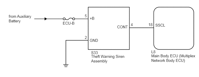
B220571E49
0.313,0.51 1.24,0.917 0.927,0.406 10 false from Auxiliary Battery 2.26,0.76 2.729,0.917 0.469,0.156 10 false ECU-B 3.052,0.49 3.198,0.646 0.146,0.156 10 false 5 4.708,0.813 4.854,0.969 0.146,0.156 10 false 4 5.344,0.813 5.531,0.969 0.188,0.156 10 false 18 3.229,0.583 3.458,0.74 0.229,0.156 10 false +B 3.052,1.281 3.198,1.438 0.146,0.156 10 false 2 3.281,1.833 3.573,1.99 0.292,0.156 10 false S33 3.281,1.969 4.594,2.375 1.313,0.406 10 false Theft Warning Siren Assembly 5.448,1.802 5.74,1.958 0.292,0.156 10 false L8 5.448,1.948 7.115,2.292 1.667,0.344 10 false Main Body ECU (Multiplex Network Body ECU) 3.229,1.385 3.563,1.542 0.333,0.156 10 false GND 4.219,0.896 4.646,1.052 0.427,0.156 10 false CONT 5.594,0.833 5.979,0.99 0.385,0.156 10 false SSCL

CAUTION / NOTICE / HINT

NOTICE:

Inspect the fuses for circuits related to this system before performing the following inspection procedure.


PROCEDURE

1.PERFORM ACTIVE TEST USING GTS
a.

Connect the GTS to the DLC3.


b.

Turn the power switch to on (IG).


c.

Turn the GTS on.


d.

Enter the following menus: Body Electrical / Main Body / Active Test.


e.

Perform the Active Test according to the display on the GTS.

Main Body
Tester Display Test Part Control Range Diagnostic Note
Security Horn2 Theft warning siren ON / OFF -

OK:

The theft warning siren assembly sounds and stops correctly when operated using the GTS.


OK

PROCEED TO NEXT SUSPECTED AREA SHOWN IN PROBLEM SYMPTOMS TABLE

NG

2.CHECK THEFT WARNING SIREN ASSEMBLY
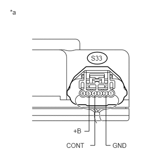
a.
U190855E02
1.955,1.163 2.243,1.300 0.288,0.137 10 S33 1.575,2.729 1.767,2.866 0.192,0.137 10 +B 0.214,0.173 0.374,0.311 0.160,0.137 10 *a 1.426,3.047 1.838,3.185 0.412,0.137 10 CONT 2.417,3.046 2.744,3.184 0.327,0.137 10 GND 1.914,2.05 1.914,2.82 1.914,2.82 1.813,2.82 false 2.277,2.05 2.277,3.124 2.277,3.124 2.375,3.124 false 2.038,2.05 2.038,3.124 2.038,3.124 1.938,3.124 false

Remove the theft warning siren assembly with harness connected (See page Vehicle Interior>THEFT DETERRENT / KEYLESS ENTRY>SECURITY HORN ASSEMBLY (for Built-in Battery type)>REMOVAL).


b.

Measure the voltage according to the value(s) in the table below.

Standard Voltage:
Tester Connection Condition Specified Condition
S33-5 (+B) - Body ground Power switch off 11 to 14 V
S33-2 (GND) - Body ground Always Below 1 V
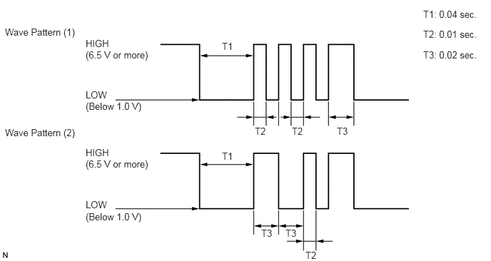
S33-4 (CONT) - Body ground When switched from armed state or arming preparation state to disarmed state (1) or disarmed state (2) (*1) Wave pattern (1) shown in chart below
When switched from arming preparation state to armed state (*2) Wave pattern (2) shown in chart below
Normal condition (Except (*1) and (*2)) 11 to 14 V


Text in Illustration
*a Component with harness connected
(Theft Warning Siren Assembly)


c.

Wave pattern

B110513E10
6.177,0.125 7,0.281 0.823,0.156 10 false T1: 0.04 sec. 1.25,0.719 2.25,0.917 1,0.198 10 false (6.5 V or more) 0.073,0.385 1.188,0.563 1.115,0.177 10 false Wave Pattern (1) 0.073,1.854 1.156,2.063 1.083,0.208 10 false Wave Pattern (2) 1.25,0.552 1.625,0.719 0.375,0.167 10 false HIGH 3.719,1.833 3.948,2 0.229,0.167 10 false T2 4.26,1.833 4.49,2 0.229,0.167 10 false T2 4.458,3.646 4.656,3.792 0.198,0.146 10 false T2 4.917,1.833 5.146,2 0.229,0.167 10 false T3 3.813,3.323 4.042,3.49 0.229,0.167 10 false T3 4.167,3.323 4.396,3.49 0.229,0.167 10 false T3 3.24,2.198 3.427,2.365 0.188,0.167 10 false T1 3.24,0.594 3.427,0.76 0.188,0.167 10 false T1 1.25,1.302 1.604,1.448 0.354,0.146 10 false LOW 1.25,1.469 2.156,1.656 0.906,0.188 10 false (Below 1.0 V) 1.25,2.313 2.25,2.51 1,0.198 10 false (6.5 V or more) 1.25,2.146 1.625,2.313 0.375,0.167 10 false HIGH 1.25,2.906 1.604,3.052 0.354,0.146 10 false LOW 1.25,3.083 2.156,3.271 0.906,0.188 10 false (Below 1.0 V) 6.177,0.417 7,0.573 0.823,0.156 10 false T2: 0.01 sec. 6.177,0.719 7,0.875 0.823,0.156 10 false T3: 0.02 sec.


OK

3.CHECK HARNESS AND CONNECTOR (MAIN BODY ECU - THEFT WARNING SIREN - BODY GROUND)

NG

3.CHECK HARNESS AND CONNECTOR (MAIN BODY ECU - THEFT WARNING SIREN - BODY GROUND)
a.

Disconnect the L8 main body ECU (multiplex network body ECU) connector.


b.

Disconnect the S33 theft warning siren assembly connector.


c.

Measure the resistance according to the value(s) in the table below.

Standard Resistance:
Tester Connection Condition Specified Condition
L8-18 (SSCL) - S33-4 (CONT) Always Below 1 Ω
L8-18 (SSCL) - Body ground Always 10 kΩ or higher
S33-2 (GND) - Body ground Always Below 1 Ω


OK

REPLACE MAIN BODY ECU (MULTIPLEX NETWORK BODY ECU)

NG

REPAIR OR REPLACE HARNESS OR CONNECTOR