Home › Vehicle Interior › THEFT DETERRENT / KEYLESS ENTRY › THEFT DETERRENT SYSTEM › 2012.03–2020.08
RM2070E _58 Vehicle Interior _061938 THEFT DETERRENT / KEYLESS ENTRY _0301770 THEFT DETERRENT SYSTEM J

THEFT DETERRENT / KEYLESS ENTRY  THEFT DETERRENT SYSTEM  Intrusion Sensor Cancel Switch Circuit  


DESCRIPTION

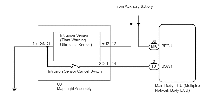
When the intrusion sensor cancel switch on the map light assembly is pressed, the sensor off signal is sent to the main body ECU (multiplex network body ECU) which causes the intrusion sensor to stop operating.


WIRING DIAGRAM
B273460E18
1.135,1.438 1.313,1.594 0.177,0.156 10 false 15 1.385,1.438 1.792,1.594 0.406,0.156 10 false GND1 1.99,2.865 2.208,3.063 0.219,0.198 10 false U3 5.281,1.552 5.552,1.802 0.271,0.25 10 false MB 5.646,1.521 6.063,1.677 0.417,0.156 10 false BECU 4.063,0.135 5.406,0.292 1.344,0.156 10 false from Auxiliary Battery 5.313,2.25 5.521,2.5 0.208,0.25 10 false L8 5.302,1.354 5.479,1.51 0.177,0.156 10 false 30 5.344,2.052 5.542,2.26 0.198,0.208 10 false 8 5.646,2.229 6.063,2.385 0.417,0.156 10 false SSW1 3.573,1.438 3.854,1.594 0.281,0.156 10 false +B2 3.906,1.438 4.083,1.594 0.177,0.156 10 false 12 3.458,2.135 3.854,2.292 0.396,0.156 10 false SOFF 2.104,1.146 3.281,1.76 1.177,0.615 10 false Intrusion Sensor (Theft Warning Ultrasonic Sensor) 1.677,2.406 3.625,2.563 1.948,0.156 10 false Intrusion Sensor Cancel Switch 1.99,3.01 3.271,3.167 1.281,0.156 10 false Map Light Assembly 3.906,2.135 4.094,2.292 0.188,0.156 10 false 14 5.417,2.906 7.063,3.25 1.646,0.344 10 false Main Body ECU (Multiplex Network Body ECU)

PROCEDURE

1.READ VALUE USING GTS
a.

Connect the GTS to the DLC3.


b.

Turn the power switch on (IG).


c.

Turn the GTS on.


d.

Enter the following menus: Body Electrical / Main Body / Data List.


e.

According to the display on the GTS, read the Data List.

Main Body
Tester Display Measurement Item/Range Normal Condition Diagnostic Note
Intrusion Sens OFF SW Intrusion sensor cancel switch/ON or OFF ON: Intrusion sensor cancel switch on
OFF: Intrusion sensor cancel switch off
-

OK:

The indicator on the GTS switches between ON and OFF in accordance with the intrusion sensor cancel switch status.


OK

REPLACE MAIN BODY ECU (MULTIPLEX NETWORK BODY ECU)

NG

2.CHECK HARNESS AND CONNECTOR (MAIN BODY ECU - MAP LIGHT ASSEMBLY)
a.

Disconnect the L8 main body ECU (multiplex network body ECU) connector.


b.

Disconnect the U3 map light assembly connector.


c.

Measure the resistance according to the value(s) in the table below.

Standard Resistance:
Tester Connection Condition Specified Condition
L8-8 (SSW1) - U3-14 (SOFF) Always Below 1 Ω
U3-15 (GND1) - Body ground Always Below 1 Ω
L8-8 (SSW1) - Body ground Always 10 kΩ or higher


OK

3.INSPECT INTRUSION SENSOR CANCEL SWITCH (MAP LIGHT ASSEMBLY)

NG

REPAIR OR REPLACE HARNESS OR CONNECTOR

3.INSPECT INTRUSION SENSOR CANCEL SWITCH (MAP LIGHT ASSEMBLY)
a.
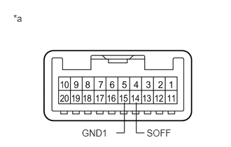
E227732E15
0.199,0.19 0.348,0.328 0.148,0.137 10 *a 1.219,1.896 1.622,2.034 0.403,0.137 10 GND1 2.183,1.896 2.571,2.034 0.388,0.137 10 SOFF 2.028,1.526 2.028,1.977 2.028,1.977 2.15,1.977 false 1.851,1.526 1.851,1.977 1.851,1.977 1.73,1.977 false

Remove the intrusion sensor cancel switch (map light assembly) (See page Vehicle Interior>LIGHTING (INT)>PERSONAL LIGHT>REMOVAL).


b.

Measure the resistance according to the value(s) in the table below.

Standard Resistance:
Tester Connection Condition Specified Condition
14 (SOFF) - 15 (GND1) Intrusion sensor cancel switch not pressed 10 kΩ or higher
14 (SOFF) - 15 (GND1) Intrusion sensor cancel switch pressed Below 1 Ω


Text in Illustration
*a Component without harness connected
(Intrusion Sensor Cancel Switch (Map Light Assembly))


OK

REPLACE MAIN BODY ECU (MULTIPLEX NETWORK BODY ECU)

NG

REPLACE INTRUSION SENSOR CANCEL SWITCH (MAP LIGHT ASSEMBLY)