RM2070E
_58
Vehicle Interior
_061943
PRE-CRASH SAFETY
_0301811
PRE-CRASH SAFETY SYSTEM
J
PRE-CRASH SAFETY PRE-CRASH SAFETY SYSTEM Pre-crash Safety Brake Cancel Switch Circuit
DESCRIPTION
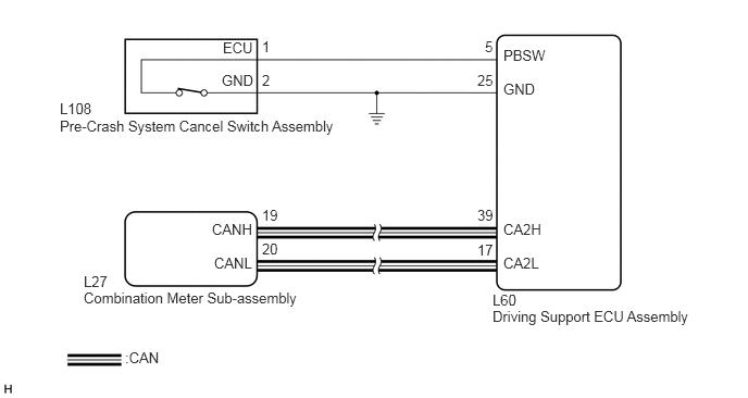
The driving support ECU assembly receives a pre-crash brake on/off signal from the pre-crash system cancel switch assembly.
WIRING DIAGRAM
1.198,3.344 1.906,3.521
0.708,0.177
10
false
:CAN
4.823,0.771 5.208,0.948
0.385,0.177
10
false
GND
4.823,0.448 5.458,0.625
0.635,0.177
10
false
PBSW
2.51,0.365 2.604,0.542
0.094,0.177
10
false
1
4.646,0.365 4.74,0.542
0.094,0.177
10
false
5
2.51,0.688 2.604,0.865
0.094,0.177
10
false
2
0.573,1.125 3.344,1.302
2.771,0.177
10
false
Pre-Crash System Cancel Switch Assembly
0.573,0.958 1.01,1.177
0.438,0.219
10
false
L108
0.802,2.771 2.917,2.948
2.115,0.177
10
false
Combination Meter Sub-assembly
0.802,2.615 1.115,2.802
0.313,0.188
10
false
L27
4.573,0.688 4.75,0.865
0.177,0.177
10
false
25
4.823,2.438 5.188,2.615
0.365,0.177
10
false
CA2L
4.823,2.115 5.208,2.292
0.385,0.177
10
false
CA2H
2.052,2.438 2.448,2.615
0.396,0.177
10
false
CANL
2.031,2.115 2.448,2.292
0.417,0.177
10
false
CANH
4.573,2.313 4.75,2.49
0.177,0.177
10
false
17
4.573,1.979 4.75,2.156
0.177,0.177
10
false
39
2.51,2.302 2.688,2.479
0.177,0.177
10
false
20
2.51,1.979 2.688,2.156
0.177,0.177
10
false
19
4.719,2.792 5.135,2.969
0.417,0.177
10
false
L60
4.719,2.948 6.771,3.125
2.052,0.177
10
false
Driving Support ECU Assembly
2.135,0.375 2.552,0.552
0.417,0.177
10
false
ECU
2.125,0.688 2.542,0.865
0.417,0.177
10
false
GND
PROCEDURE
1.READ VALUE USING GTS (PRE-CRASH SYSTEM CANCEL SWITCH ASSEMBLY)
a.
Connect the GTS to the DLC3.
b.
Turn the power switch on (IG).
c.
Turn the GTS on.
d.
Enter the following menus: Body Electrical / Pre-Crash 2 / Data List.
e.
Read the display on the GTS.
| Tester Display | Measurement Item/Range | Normal Condition | Diagnostic Note |
|---|---|---|---|
| Pre-Crash Brake OFF Switch | Pre-crash system cancel switch assembly signal/ON or OFF | ON: Pre-crash system cancel switch assembly on
OFF: Pre-crash system cancel switch assembly off |
- |
- OK:
On screen, each item changes between ON and OFF according to above chart.
OK
PROCEED TO NEXT SUSPECTED AREA SHOWN IN PROBLEM SYMPTOMS TABLE
NG
2.INSPECT PRE-CRASH SYSTEM CANCEL SWITCH ASSEMBLY
2.INSPECT PRE-CRASH SYSTEM CANCEL SWITCH ASSEMBLY
a.
0.16,0.084 0.323,0.239
0.163,0.156
10
*a
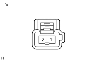
Remove the pre-crash system cancel switch assembly (See page Vehicle Interior>PRE-CRASH SAFETY>PRE-CRASH BRAKE CANCEL SWITCH>REMOVAL).
b.
Measure the resistance according to the value(s) in the table below.
- Standard Resistance:
Tester Connection Switch Condition Specified Condition 1 - 2 Pressed Below 1 Ω Not pressed 10 kΩ or higher
| *a | Component without harness connected
(Pre-crash system cancel switch assembly) |
OK
3.CHECK HARNESS AND CONNECTOR (PRE-CRASH SYSTEM CANCEL SWITCH ASSEMBLY - DRIVING SUPPORT ECU ASSEMBLY, BODY GROUND)
NG
REPLACE PRE-CRASH SYSTEM CANCEL SWITCH ASSEMBLY
3.CHECK HARNESS AND CONNECTOR (PRE-CRASH SYSTEM CANCEL SWITCH ASSEMBLY - DRIVING SUPPORT ECU ASSEMBLY, BODY GROUND)
a.
Disconnect the L60 driving support ECU assembly connector.
b.
Measure the resistance according to the value(s) in the table below.
- Standard Resistance:
Tester Connection Condition Specified Condition L108-1 (ECU) - L60-5 (PBSW) Always Below 1 Ω L108-1 (ECU) - Body ground Always 10 kΩ or higher L108-2 (GND) - Body ground Always Below 1 Ω L60-25 (GND) - Body ground Always Below 1 Ω
OK
REPLACE DRIVING SUPPORT ECU ASSEMBLY
NG
REPAIR OR REPLACE HARNESS OR CONNECTOR (PRE-CRASH SYSTEM CANCEL SWITCH - DRIVING SUPPORT ECU)