DOOR / HATCH BACK DOOR ADJUSTMENT
CAUTION / NOTICE / HINT
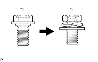
| *1 | Centering Bolt |
| *2 | Standard Bolt |
- HINT:
- ·
Use the same procedure for the RH side and LH side.
·The following procedure is for the LH side.
·Centering bolts are used to mount the door hinge to the vehicle body and door. The door cannot be adjusted with the centering bolts installed. Substitute the centering bolts with standard bolts (with washers) when making adjustments.
·Specified torque for standard bolts is shown in the standard bolt chart (See page General>SPECIFICATIONS>STANDARD BOLT>SPECIFIED TORQUE FOR STANDARD BOLTS).
PROCEDURE

 1.INSPECT BACK DOOR
Check that the clearance measurements of areas *a through *j are within each standard range.
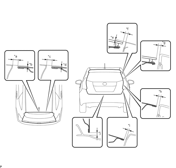
| Area | Measurement | Area | Measurement |
|---|---|---|---|
| *a | 6.2 to 9.2 mm (0.244 to 0.362 in.) | *b | -0.1 to 2.9 mm (-0.00394 to 0.114 in.) |
| *c | 6.2 to 9.2 mm (0.244 to 0.362 in.) | *d | -0.1 to 2.9 mm (-0.00394 to 0.114 in.) |
| *e | 0.05 to 4.05 mm (0.00197 to 0.159 in.) | *f | 2.85 to 6.85 mm (0.112 to 0.270 in.) |
| *g | 3.0 to 7.0 mm (0.118 to 0.276 in.) | *h | 3.0 to 7.0 mm (0.118 to 0.276 in.) |
| *i | 4.0 to 8.0 mm (0.157 to 0.315 in.) | *j | 4.0 to 8.0 mm (0.157 to 0.315 in.) |
58410B
2.REMOVE DECK BOARD ASSEMBLY
58412A
3.REMOVE NO. 2 DECK BOARD
64993
4.REMOVE REAR DECK FLOOR BOX
67935A
5.REMOVE BACK DOOR SCUFF PLATE
6.ADJUST BACK DOOR
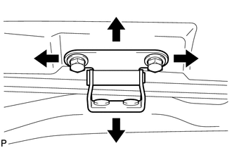
Before adjusting the upper end of the back door up and down or left and right, loosen the bolts.
Tighten the body side hinge after adjustment.
- Torque:
- 19 N*m (194 kgf*cm, 14 ft.*lbf)
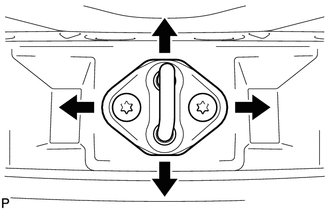
Using a T40 "TORX" socket wrench, slightly loosen the striker mounting screws.
Using a brass bar and a hammer, hit the striker to adjust its position.
Using a T40 "TORX" socket wrench, tighten the striker mounting screws after adjustment.
- Torque:
- 23 N*m (235 kgf*cm, 17 ft.*lbf)
67935A
7.INSTALL BACK DOOR SCUFF PLATE
64993
8.INSTALL REAR DECK FLOOR BOX
58412A
9.INSTALL NO. 2 DECK BOARD
58410B
10.INSTALL DECK BOARD ASSEMBLY