RM2070E
_59
Vehicle Exterior
_061952
WIPER / WASHER
_0301891
WIPER AND WASHER SYSTEM
J
WIPER / WASHER WIPER AND WASHER SYSTEM Headlight Cleaner Switch Circuit
DESCRIPTION
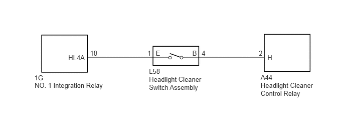
This circuit detects the conditions (on or off) of the headlight cleaner switch assembly.
WIRING DIAGRAM
0.714,1.535 1.049,1.693
0.335,0.158
10
1G
1.419,1.113 1.786,1.271
0.367,0.158
10
HL4A
3.236,1.024 3.347,1.182
0.111,0.158
10
E
1.87,1.024 2.043,1.182
0.172,0.158
10
10
3.06,1.024 3.155,1.182
0.094,0.158
10
1
4.189,1.024 4.286,1.182
0.097,0.158
10
4
3.996,1.024 4.107,1.182
0.112,0.158
10
B
5.555,1.113 5.673,1.271
0.117,0.158
10
H
5.378,1.024 5.472,1.182
0.094,0.158
10
2
3.096,1.393 3.346,1.550
0.250,0.158
10
L58
3.096,1.561 4.231,1.880
1.135,0.319
10
Headlight Cleaner Switch Assembly
5.415,1.523 5.680,1.681
0.265,0.158
10
A44
5.415,1.691 6.550,2.010
1.135,0.319
10
Headlight Cleaner Control Relay
0.719,1.685 2.388,1.842
1.670,0.158
10
NO. 1 Integration Relay
PROCEDURE
1.INSPECT HEADLIGHT CLEANER CONTROL RELAY
a.
Disconnect the A44 headlight cleaner control relay connector.
b.
Measure the voltage according to the value(s) in the table below.
- Standard Voltage:
Tester Connection Condition Specified Condition A44-2 (H) - Body ground Light control switch off and headlight cleaner switch on 11 to 14 V A44-2 (H) - Body ground Headlight cleaner switch off Below 1 V
OK
PROCEED TO NEXT SUSPECTED AREA SHOWN IN PROBLEM SYMPTOMS TABLE
NG
2.INSPECT HEADLIGHT CLEANER SWITCH ASSEMBLY
2.INSPECT HEADLIGHT CLEANER SWITCH ASSEMBLY
a.
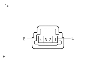
Remove the headlight cleaner switch assembly (See page Vehicle Exterior>WIPER / WASHER>HEADLIGHT CLEANER SWITCH>REMOVAL).
0.175,0.107 0.477,0.353
0.302,0.246
10
*a
0.816,1.311 0.965,1.488
0.149,0.177
10
B
2.561,1.294 2.709,1.470
0.149,0.177
10
E
2.029,1.389 2.527,1.389
false
1.411,1.39 0.96,1.39
false
b.
Measure the resistance according to the value(s) in the table below.
- Standard Resistance:
Tester Connection Switch Condition Specified Condition 1 (E) - 4 (B) Headlight cleaner switch off 10 kΩ or higher 1 (E) - 4 (B) Headlight cleaner switch on Below 1 Ω
| *a | Component without harness connected
(Headlight Cleaner Switch Assembly) |
OK
3.CHECK HARNESS AND CONNECTOR (HEADLIGHT CLEANER SWITCH ASSEMBLY - HEADLIGHT CLEANER CONTROL RELAY)
NG
REPLACE HEADLIGHT CLEANER SWITCH ASSEMBLY
3.CHECK HARNESS AND CONNECTOR (HEADLIGHT CLEANER SWITCH ASSEMBLY - HEADLIGHT CLEANER CONTROL RELAY)
a.
Measure the resistance according to the value(s) in the table below.
- Standard Resistance:
Tester Connection Switch Condition Specified Condition L58-4 (B) - A44-2 (H) Always Below 1 Ω L58-4 (B) - Body ground Always 10 kΩ or higher
OK
4.CHECK HARNESS AND CONNECTOR (NO. 1 INTEGRATION RELAY - HEADLIGHT CLEANER SWITCH ASSEMBLY)
NG
REPAIR OR REPLACE HARNESS OR CONNECTOR
4.CHECK HARNESS AND CONNECTOR (NO. 1 INTEGRATION RELAY - HEADLIGHT CLEANER SWITCH ASSEMBLY)
a.
Disconnect the 1G No. 1 integration relay connector.
b.
Measure the resistance according to the value(s) in the table below.
- Standard Resistance:
Tester Connection Switch Condition Specified Condition 1G-10 (HL4A) - L58-1 (E) Always Below 1 Ω 1G-10 (HL4A) - Body ground Always 10 kΩ or higher
OK
REPLACE NO. 1 INTEGRATION RELAY
NG
REPAIR OR REPLACE HARNESS OR CONNECTOR