EXTERIOR PANELS / TRIM FRONT BUMPER DISASSEMBLY
PROCEDURE

 89341A
1.REMOVE NO. 1 ULTRASONIC SENSOR (w/ Intelligent Parking Assist System)
89348
2.REMOVE NO. 1 ULTRASONIC SENSOR RETAINER (w/ Intelligent Parking Assist System)
81440B
3.REMOVE DAYTIME RUNNING LIGHT ASSEMBLY LH
81430C
4.REMOVE DAYTIME RUNNING LIGHT ASSEMBLY RH
- HINT:
-
Use the same procedure as for the LH side.
82113
5.REMOVE NO. 3 ENGINE ROOM WIRE
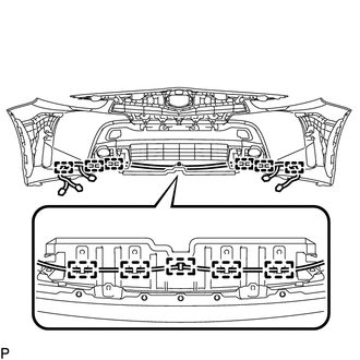
Disengage the 11 clamps to remove the No. 3 engine room wire.
81220
6.REMOVE FOG LIGHT ASSEMBLY LH
81210A
7.REMOVE FOG LIGHT ASSEMBLY RH
- HINT:
-
Use the same procedure as for the LH side.
53395E
8.REMOVE HOOD TO FRONT END PANEL SEAL
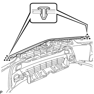
Disengage the 2 clips and remove the hood to front end panel seal.
75301A
9.REMOVE FRONT BUMPER EMBLEM SUB-ASSEMBLY
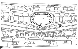
Remove the 2 screws.
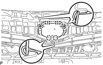
Disengage the 4 claws and 2 pins to remove the front bumper emblem sub-assembly.
53111
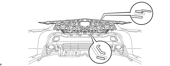
10.REMOVE RADIATOR GRILLE
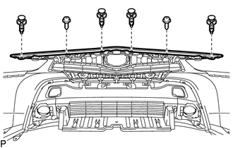
Remove the 2 screws.
Remove the 4 clips.
Disengage the 16 claws and guide to remove the radiator grille.
53113E
11.REMOVE LOWER NO. 2 RADIATOR GRILLE
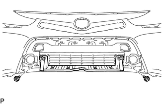
Remove the 2 screws.
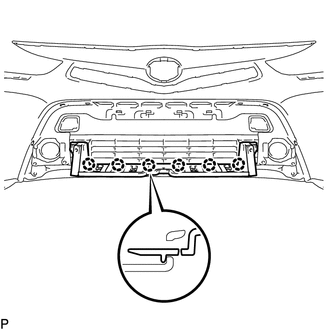
Disengage the 6 claws to remove the lower No. 2 radiator grille.
53102A
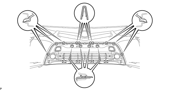
12.REMOVE LOWER RADIATOR GRILLE SUB-ASSEMBLY
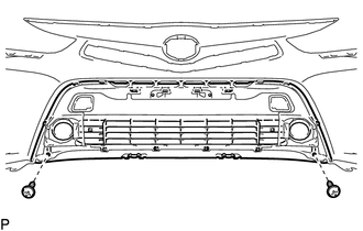
Remove the 2 screws.
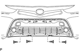
Remove the 4 outside moulding retainers.
Disengage the 14 claws and 4 guides to remove the lower radiator grille sub-assembly.
52128B
13.REMOVE FRONT BUMPER HOLE COVER LH
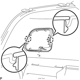
Disengage the 2 claws.
| *a | Hook |
Disengage the hook to remove the front bumper hole cover LH.
52127C
14.REMOVE FRONT BUMPER HOLE COVER RH
- HINT:
-
Use the same procedure as for the LH side.
52822
15.REMOVE AIR INTAKE DUCT LH
- HINT:
-
Use the same procedure as for the LH side.
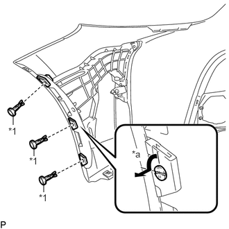
Using a screwdriver, turn the pin 90 degrees and remove the 3 pin hold clips.
| *1 | Pin Hold Clip |
| *a | 90° |
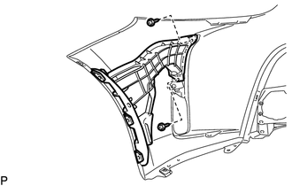
Remove the 2 screws and air intake duct LH.
52821
16.REMOVE AIR INTAKE DUCT RH
- HINT:
-
Use the same procedure as for the LH side.
53879A
17.REMOVE FRONT FENDER LINER RETAINER
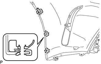
Disengage the claw to remove the 3 front fender liner retainers.
- HINT:
-
Use the same procedure for the RH side and LH side.
52113D
18.REMOVE FRONT BUMPER EXTENSION LH
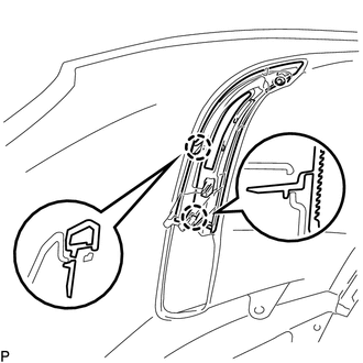
Disengage the 2 claws to remove the front bumper extension LH.
52112D
19.REMOVE FRONT BUMPER EXTENSION RH
- HINT:
-
Use the same procedure for the RH side and LH side.
52611
20.REMOVE FRONT BUMPER ENERGY ABSORBER
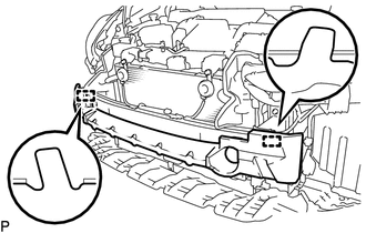
Disengage the 2 guides to remove the front bumper energy absorber.
52021
21.REMOVE FRONT BUMPER REINFORCEMENT SUB-ASSEMBLY
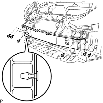
Using a clip remover, disengage the 3 clamps.
Remove the 6 bolts.
Disengage the claw and remove the front bumper reinforcement sub-assembly.
52116A
22.REMOVE FRONT BUMPER SIDE SUPPORT LH
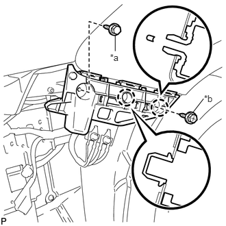
Remove the bolt and screw.
| *a | Bolt |
| *b | Screw |
Disengage the 2 claws and remove the front bumper side support LH.
52115A
23.REMOVE FRONT BUMPER SIDE SUPPORT RH
- HINT:
-
Use the same procedure as for the LH side.
57014A
24.REMOVE FRONT SIDE MEMBER BRACKET SUB-ASSEMBLY LH
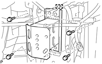
Remove the 4 bolts.
Disengage the guide and remove the front side member bracket sub-assembly LH.
57013C
25.REMOVE FRONT SIDE MEMBER BRACKET SUB-ASSEMBLY RH
- HINT:
-
Use the same procedure as for the LH side.