EXTERIOR PANELS / TRIM FRONT DOOR WINDOW FRAME MOULDING INSTALLATION
PROCEDURE

 1. PRECAUTION
- NOTICE:
-
After turning the power switch off, waiting time may be required before disconnecting the cable from the negative (-) auxiliary battery terminal. Therefore, make sure to read the disconnecting the cable from the negative (-) auxiliary battery terminal notices before proceeding with work (See page General>INTRODUCTION>REPAIR INSTRUCTION>PRECAUTION).
75756C
2.INSTALL FRONT DOOR REAR WINDOW FRAME MOULDING
- HINT:
-
When installing the front door rear window frame moulding, heat the vehicle body and front door rear window frame moulding using a heat light.
| Item | Temperature |
|---|---|
| Vehicle Body | 40 to 60°C (104 to 140°F) |
| Moulding | 20 to 30°C (68 to 86°F) |
- NOTICE:
-
Do not heat the vehicle body or front door rear window frame moulding excessively.
Clean the vehicle body surface.
Using a heat light, heat the vehicle body surface.
Remove the double-sided tape from the vehicle body.
Wipe off any tape adhesive residue with cleaner.
Clean the front door rear window frame moulding (if reusing the front door rear window frame moulding).
Using a heat light, heat the front door rear window frame moulding.
Remove the double-sided tape from the front door rear window frame moulding.
Wipe off any tape adhesive residue with cleaner.
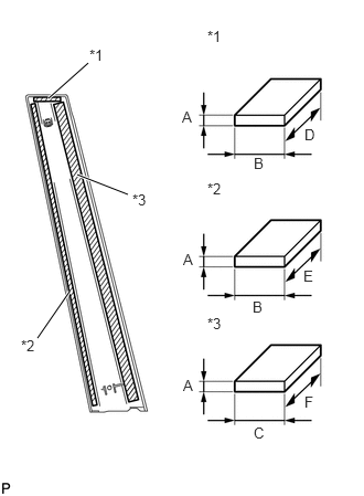
Apply new double-sided tape to the front door rear window frame moulding.
| *1 | Double-sided Tape (A) |
| *2 | Double-sided Tape (B) |
| *3 | Double-sided Tape (C) |
| Item | Dimension |
|---|---|
| A | 0.8 mm (0.0315 in.) |
| B | 5.0 mm (0.197 in.) |
| C | 15.0 mm (0.591 in.) |
| D | 40.0 mm (1.57 in.) |
| E | 455.0 mm (1.49 ft.) |
| F | 450.0 mm (1.48 ft.) |
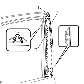
Install the front door rear window frame moulding.
| *1 | Double-sided Tape |
Using a heat light, heat the vehicle body and front door rear window frame moulding.
Remove the release paper from the face of the front door rear window frame moulding.
- HINT:
-
After removing the release paper, keep the exposed adhesive free from foreign matter.
Engage the clip and guide to install the front door rear window frame moulding.
75720
3.INSTALL FRONT DOOR BELT MOULDING ASSEMBLY
68151D
4.INSTALL FRONT DOOR GLASS RUN
68102
5.INSTALL FRONT DOOR GLASS SUB-ASSEMBLY
67832
6.INSTALL FRONT DOOR SERVICE HOLE COVER
67626
7.INSTALL FRONT DOOR TRIM BRACKET
67602
8.INSTALL FRONT DOOR TRIM BOARD SUB-ASSEMBLY
74222
9.INSTALL DOOR ARMREST COVER
10.INSTALL MULTIPLEX NETWORK MASTER SWITCH ASSEMBLY WITH FRONT DOOR ARMREST BASE PANEL (for Driver Side)
11.INSTALL POWER WINDOW REGULATOR SWITCH ASSEMBLY WITH FRONT DOOR ARMREST BASE PANEL (for Front Passenger Side)
69284C
12.INSTALL FRONT DOOR INSIDE HANDLE BEZEL PLUG
13.CONNECT CABLE TO NEGATIVE AUXILIARY BATTERY TERMINAL
- NOTICE:
-
When disconnecting the cable, some systems need to be initialized after the cable is reconnected (See page General>INTRODUCTION>REPAIR INSTRUCTION>INITIALIZATION).
64995
14.INSTALL DECK FLOOR BOX RH
64993
15.INSTALL REAR DECK FLOOR BOX
58411A
16.INSTALL NO. 1 DECK BOARD
58412A
17.INSTALL NO. 2 DECK BOARD
58410B
18.INSTALL DECK BOARD ASSEMBLY
19.INITIALIZE POWER WINDOW CONTROL SYSTEM
20.INSPECT POWER WINDOW OPERATION