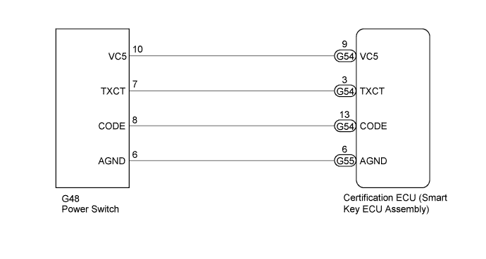
DTC B2784 Antenna Coil Open / Short |
| DTC Code | DTC Detection Condition | Trouble Area | DTC Output Confirmation Operation |
| B2784 | The transponder key amplifier coil built into the power switch is open (see below) or shorted (determined by communication with certification ECU (smart key ECU assembly)) (1 trip detection logic*).
|
| With the shift lever in P, the key held near the power switch and a hybrid control system start operation is performed by pressing and holding the power switch when the key battery is depleted. |
| Vehicle Condition when Malfunction Detected | Fail-safe Operation when Malfunction Detected |
| Hybrid control system cannot be started when key battery is depleted by holding key near power switch and pressing and holding power switch with shift lever in P | - |
| DTC Code | Data List and Active Test |
| B2784 | - |
| 1.CHECK HARNESS AND CONNECTOR (CERTIFICATION ECU (SMART KEY ECU ASSEMBLY) - POWER SWITCH) |
Disconnect the G55 and G54 certification ECU (smart key ECU assembly) connector.
Disconnect the G48 power switch connector.
Measure the resistance according to the value(s) in the table below.
| Tester Connection | Condition | Specified Condition |
| G54-13 (CODE) - G48-8 (CODE) | Always | Below 1 Ω |
| G54-3 (TXCT) - G48-7 (TXCT) | Always | Below 1 Ω |
| G54-9 (VC5) - G48-10 (VC5) | Always | Below 1 Ω |
| G55-6 (AGND) - G48-6 (AGND) | Always | Below 1 Ω |
| G48-8 (CODE) - Body ground | Always | 10 kΩ or higher |
| G48-7 (TXCT) - Body ground | Always | 10 kΩ or higher |
| G48-10 (VC5) - Body ground | Always | 10 kΩ or higher |
| G48-6 (AGND) - Body ground | Always | 10 kΩ or higher |
|
| ||||
| OK | |
 |
| 2.REPLACE POWER SWITCH |
Temporarily replace the power switch with a new or known good one (Click here).
| NEXT | |
|
| 3.CLEAR DTC |
Clear the DTCs (Click here).
| NEXT | |
|
| 4.CHECK DTC OUTPUT |
Check for DTCs (Click here).
|
| ||||
| OK | ||
 | ||
| ||
