 |
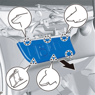
Disengage the 4 claws and 2 clips as shown in the illustration.
OUTER MIRROR SWITCH > REMOVAL |
| 1. REMOVE UPPER INSTRUMENT PANEL SUB-ASSEMBLY |
| 2. REMOVE NO. 1 SWITCH HOLE BASE |
|
Disengage the 4 claws and 2 clips as shown in the illustration.
Disconnect each connector and remove the No. 1 switch hole base.
| 3. REMOVE OUTER MIRROR SWITCH ASSEMBLY |
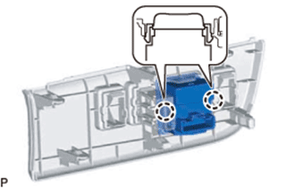 |
Disengage the 2 claws and remove the outer mirror switch assembly.