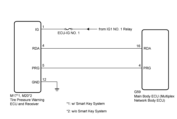
DTC B1247 Tire Pressure Monitor Receiver Communication Stop |
| DTC No. | DTC Detection Condition | Trouble Area |
| B1247 | In diagnostic mode, an applicable RDA signal cannot be received within 2.4 seconds after a PRG signal is sent from the main body ECU (multiplex network body ECU). |
|
| 1.CHECK HARNESS AND CONNECTOR (MAIN BODY ECU (MULTIPLEX NETWORK BODY ECU) - TIRE PRESSURE WARNING ECU AND RECEIVER) |
Disconnect the tire pressure warning ECU and receiver M17 or M20 connector and main body ECU (multiplex network body ECU) G59 connector.
Measure the resistance according to the value(s) in the table below.
| Tester Connection | Condition | Specified Condition |
| M17-4 (RDA) - G59-16 (RDA)*1 M20-4 (RDA) - G59-16 (RDA)*2 | Always | Below 1 Ω |
| G59-16 (RDA) - Body ground | Always | 10 kΩ or higher |
|
| ||||
| OK | |
 |
| 2.CHECK HARNESS AND CONNECTOR (POWER SOURCE OF TIRE PRESSURE WARNING ECU AND RECEIVER) |
Measure the resistance according to the value(s) in the table below.
| Tester Connection | Condition | Specified Condition |
| M17-12 (GND) - Body ground*1 M20-12 (GND) - Body ground*2 | Always | Below 1 Ω |
Measure the voltage according to the value(s) in the table below.
| Tester Connection | Condition | Specified Condition |
| M17-1 (IG) - Body ground*1 M20-1 (IG) - Body ground*2 | Ignition switch ON | 10 to 16 V |
|
| ||||
| OK | |
|
| 3.REPLACE TIRE PRESSURE WARNING ECU AND RECEIVER |
Replace the tire pressure warning ECU and receiver (Click here).
| NEXT | |
|
| 4.CHECK DTC OUTPUT (B1247) |
Clear the DTCs (Click here).
Turn the ignition switch off.
Turn the ignition switch to ON.
Check for DTCs (Click here).
|
| ||||
| OK | ||
 | ||
| ||
