 |
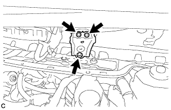
Remove the 3 bolts and inner cowl top to cowl brace.
AIR CONDITIONING UNIT > REMOVAL |
| 1. PRECAUTION |
| 2. RECOVER REFRIGERANT FROM AIR CONDITIONING SYSTEM |
Start the hybrid system.
Operate the cooler compressor under the conditions show below:
| Item | Condition |
| Engine Speed | Idling |
| Operating Time | 3 minutes or more |
| A/C Switch Status | ON |
| Blower Switch Status | HI |
| Set Temperature | MAX COOL |
Stop the engine.
Recover the refrigerant from the A/C system using a refrigerant recovery unit.
| 3. REMOVE WINDSHIELD WIPER MOTOR AND LINK |
| 4. REMOVE INNER COWL TOP TO COWL BRACE |
|
Remove the 3 bolts and inner cowl top to cowl brace.
| 5. REMOVE FRONT AIR SHUTTER SEAL |
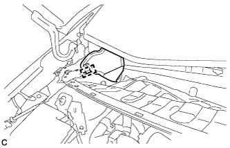 |
Disengage the clamp to remove the front air shutter seal.
| 6. REMOVE FRONT NO. 1 VENTILATOR SEAL |
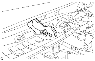 |
Disengage the clamp to remove the front No. 1 ventilator seal.
| 7. REMOVE OUTER COWL TOP PANEL SUB-ASSEMBLY |
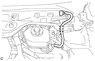 |
Disengage the clamp to separate the wire harness from the outer cowl top panel sub-assembly.
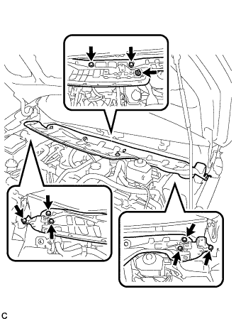 |
Remove the 8 bolts, nut and outer cowl top panel sub-assembly.
| 8. DISCONNECT SUCTION PIPE SUB-ASSEMBLY |
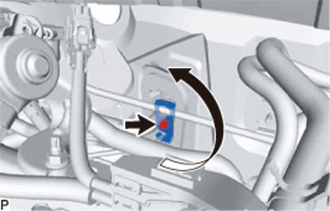 |
Remove the bolt and rotate the hook connector.
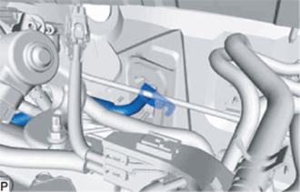 |
Disconnect the suction pipe sub-assembly.
Remove the O-ring from the suction pipe sub-assembly.
| 9. DISCONNECT LIQUID PIPE SUB-ASSEMBLY |
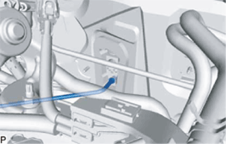 |
Disconnect the liquid pipe sub-assembly.
Remove the O-ring from the liquid pipe sub-assembly.
| 10. DISCONNECT HEATER WATER OUTLET HOSE A |
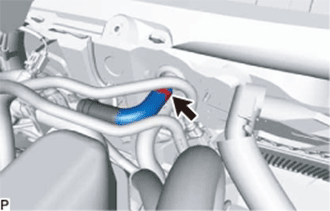 |
Using pliers, grip the claws of the clip and slide the clip to disconnect the heater water outlet hose A.
| 11. DISCONNECT WATER HOSE SUB-ASSEMBLY |
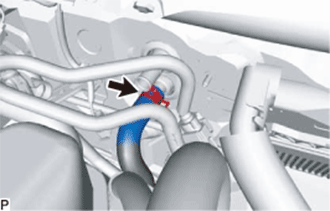 |
Using pliers, grip the claws of the clip and slide the clip to disconnect the water hose sub-assembly.
| 12. REMOVE LOWER INSTRUMENT PANEL SUB-ASSEMBLY |
| 13. REMOVE STEERING COLUMN ASSEMBLY |
| 14. REMOVE FRONT SEAT ASSEMBLY LH (for Cold Area Specification Vehicles) |
| 15. REMOVE FRONT SEAT ASSEMBLY RH (for Cold Area Specification Vehicles) |
| 16. REMOVE POWER MANAGEMENT CONTROL ECU |
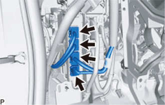 |
Disconnect the 4 connectors.
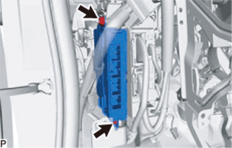 |
Remove the 2 nuts and power management control ECU.
| 17. DISCONNECT INSTRUMENT PANEL WIRE |
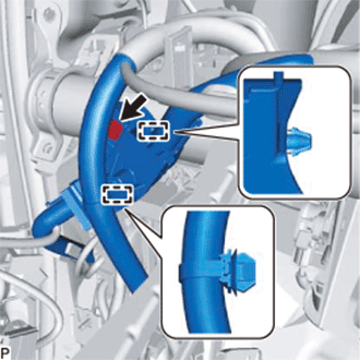 |
Remove the bolt.
Disengage the 2 clamps and disconnect the instrument panel wire.
| 18. REMOVE INSTRUMENT PANEL JUNCTION BLOCK ASSEMBLY |
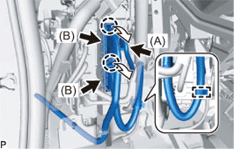 |
Disengage the clamp.
Disconnect the connector (A).
Disengage the 2 claws and disconnect the 2 connectors (B).
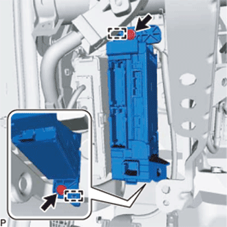 |
Remove the 2 bolts.
Disengage the 2 clamps and pull out the instrument panel junction block assembly.
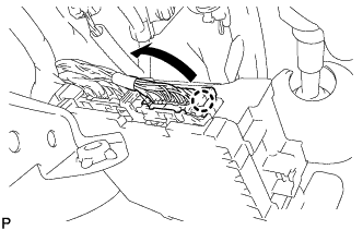 |
Disengage the claw and disconnect the connector as shown in the illustration.
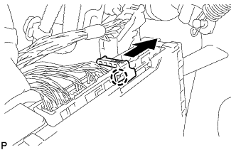 |
Disengage the claw and release the connector lock as shown in the illustration.
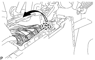 |
Disengage the claw and disconnect the connector as shown in the illustration to remove the instrument panel junction block assembly.
| 19. REMOVE POWER STEERING ECU ASSEMBLY |
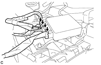 |
Disconnect the 4 connectors from the power steering ECU assembly.
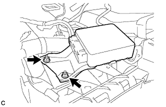 |
Remove the 2 nuts and power steering ECU assembly.
| 20. REMOVE VEHICLE APPROACHING SPEAKER CONTROLLER |
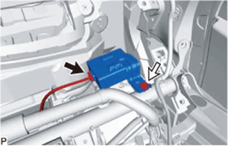 |
Disconnect the connector.
Remove the bolt and vehicle approaching speaker controller.
| 21. REMOVE NO. 1 INDOOR ELECTRICAL KEY ANTENNA ASSEMBLY (w/ Smart Key System) |
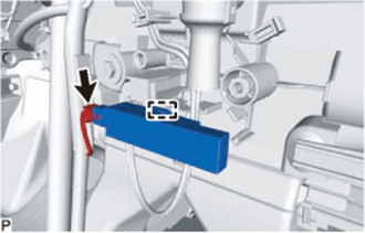 |
Disconnect the connector.
Disengage the clamp and remove the No. 1 indoor electrical key antenna assembly.
| 22. REMOVE NO. 2 INDOOR ELECTRICAL KEY ANTENNA ASSEMBLY (w/ Smart Key System) |
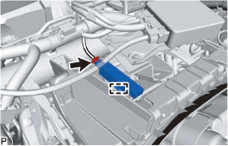 |
Disconnect the connector.
Disengage the clamp and remove the No. 2 indoor electrical key antenna assembly.
| 23. DISCONNECT FRONT FLOOR CARPET ASSEMBLY (except Cold Area Specification Vehicles) |
Turn back the front floor carpet assembly.
| 24. DISCONNECT FUEL LID LOCK OPEN LEVER SUB-ASSEMBLY (for Cold Area Specification Vehicles) |
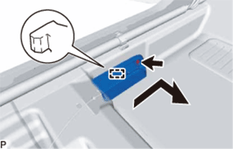 |
Remove the screw.
Disengage the guide and disconnect the fuel lid lock open lever sub-assembly as shown in the illustration.
| 25. REMOVE FRONT FLOOR CAUTION PLATE COVER (for Cold Area Specification Vehicles) |
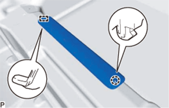 |
Disengage the claw and guide, and remove the front floor caution plate cover.
| 26. REMOVE JACK COVER (for Cold Area Specification Vehicles) |
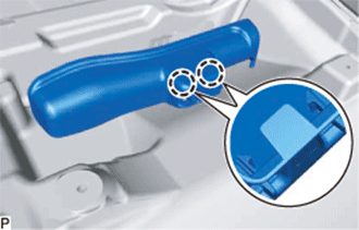 |
Disengage the 2 claws and remove the jack cover.
| 27. REMOVE JACK ASSEMBLY (for Cold Area Specification Vehicles) |
Remove the jack assembly.
| 28. REMOVE REAR NO. 3 AIR DUCT (for Cold Area Specification Vehicles) |
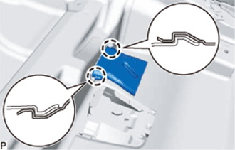 |
Disengage the 2 claws and remove the rear No. 3 air duct.
| 29. REMOVE FRONT FLOOR CARPET ASSEMBLY (for Cold Area Specification Vehicles) |
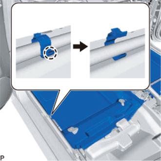 |
Disengage the claw and disconnect the front floor carpet assembly.
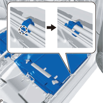 |
Disengage the claw and disconnect the front floor carpet assembly.
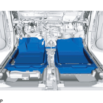 |
Remove the front floor carpet assembly.
| 30. REMOVE REAR NO. 2 AIR DUCT (for Cold Area Specification Vehicles) |
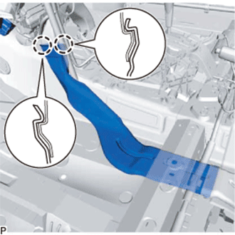 |
Disengage the 2 claws and remove the rear No. 2 air duct.
| 31. REMOVE REAR NO. 4 AIR DUCT (for Cold Area Specification Vehicles) |
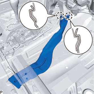 |
Disengage the 2 claws and remove the rear No. 4 air duct.
| 32. REMOVE REAR NO. 1 AIR DUCT (for Cold Area Specification Vehicles) |
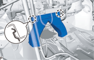 |
Disengage the 2 claws and remove the rear No. 1 air duct.
| 33. REMOVE NO. 1 INSTRUMENT PANEL BRACE SUB-ASSEMBLY |
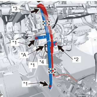 |
Disengage each clamp.
| *A | for Cold Area Specification Vehicles |
| *1 | Bolt |
| *2 | Screw |
| *3 | Nut |
| *4 | Earth Wire |
for Cold Area Specification Vehicles:
Remove the bolt and disconnect the earth wire.
Remove the 2 bolts, screw, nut and No. 1 instrument panel brace sub-assembly.
| 34. DISCONNECT INSTRUMENT PANEL WIRE |
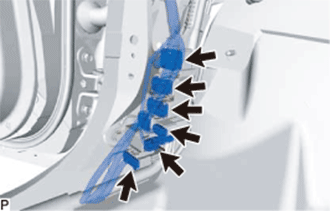 |
for LH Side:
Disconnect each connector.
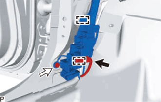 |
Disconnect the connector from the connector holder.
Remove the bolt.
Disengage each clamp and disconnect the connector holder.
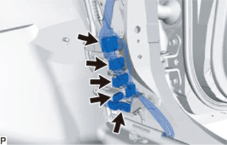 |
for RH Side:
Disconnect each connector.
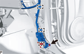 |
Remove the bolt.
Disengage each clamp and disconnect the connector holder.
Remove the 2 bolts <A> and disconnect the 2 earth wires.
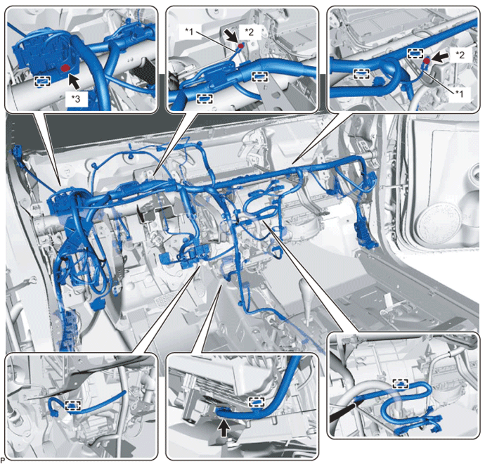
| *1 | Earth Wire | *2 | Bolt <A> |
| *3 | Bolt <B> | - | - |
Remove the bolt <B>.
Disconnect the connector.
Disengage each clamp.
Remove the bolt and disconnect the earth wire.
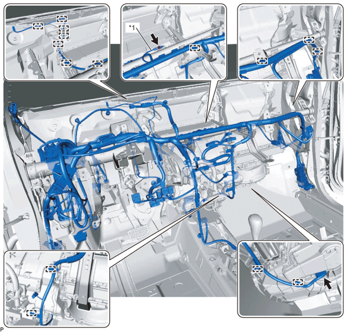
| *1 | Earth Wire | - | - |
Disconnect the connector.
Disengage each clamp and disconnect the instrument panel wire.
| 35. REMOVE INSTRUMENT PANEL REINFORCEMENT ASSEMBLY |
Remove the 8 bolts and 3 screws, and remove the instrument panel reinforcement.
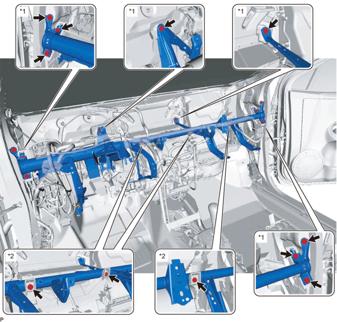
| *1 | Bolt | *2 | Screw |
| 36. REMOVE DEFROSTER NOZZLE ASSEMBLY |
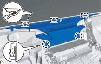 |
Disengage the 2 claws and 3 guides and remove the defroster nozzle assembly.
| 37. DISCONNECT DRAIN COOLER HOSE |
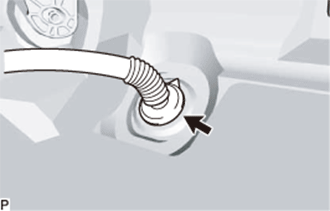 |
Disconnect the drain cooler hose.
| 38. REMOVE AIR CONDITIONER UNIT ASSEMBLY |
Remove the 3 bolts and nut, and remove the air conditioner unit assembly.
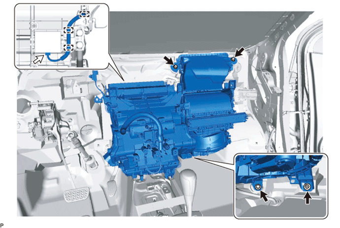
Disconnect the connector.
Disengage the 3 clamps.
| 39. REMOVE AIR CONDITIONING RADIATOR ASSEMBLY |
Disconnect the connector.
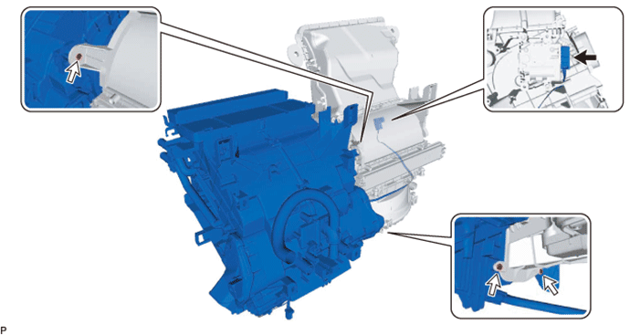
Remove the 3 screws and air conditioning radiator assembly.
| 40. REMOVE ASPIRATOR |
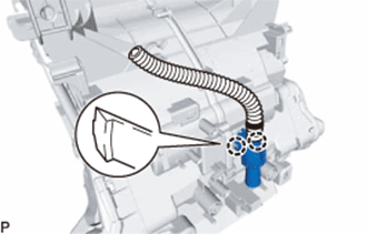 |
Disengage the 2 claws and remove the aspirator.
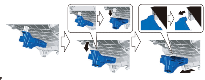
| 41. REMOVE AIR CONDITIONING AMPLIFIER ASSEMBLY |
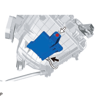 |
Disconnect the connector.
Remove the screw.
Remove the air conditioning amplifier assembly as shown in the illustration.
| 42. REMOVE AIR CONDITIONING HARNESS ASSEMBLY |
Disengage each clamp.
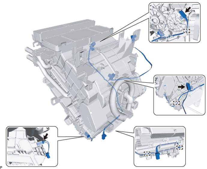
Disconnect each connector and remove the air conditioning harness assembly.
| 43. REMOVE NO. 3 AIR DUCT SUB-ASSEMBLY |
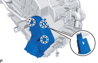 |
Disengage the 3 claws and remove the No. 3 air duct sub-assembly.
| 44. REMOVE NO. 2 AIR DUCT SUB-ASSEMBLY |
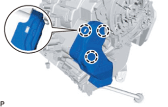 |
Disengage the 3 claws and remove the No. 2 air duct sub-assembly.
| 45. REMOVE TRANSPONDER KEY ECU ASSEMBLY (w/o Smart Key System) |
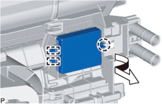 |
Disengage the claw and 2 guides and remove the transponder key ECU assembly.
| 46. REMOVE ID CODE BOX (IMMOBILIZER CODE ECU) (w/ Smart Key System) |
|
Disengage the claw and 2 guides and remove the ID code box (immobiliser code ECU).