| B |  |
| GO TO DTC CHART (P0AFC-123) (Click here) |
DTC P3011-123 Battery Block 1 Becomes Weak |
DTC P3012-123 Battery Block 2 Becomes Weak |
DTC P3013-123 Battery Block 3 Becomes Weak |
DTC P3014-123 Battery Block 4 Becomes Weak |
DTC P3015-123 Battery Block 5 Becomes Weak |
DTC P3016-123 Battery Block 6 Becomes Weak |
DTC P3017-123 Battery Block 7 Becomes Weak |
DTC P3018-123 Battery Block 8 Becomes Weak |
DTC P3019-123 Battery Block 9 Becomes Weak |
DTC P3020-123 Battery Block 10 Becomes Weak |
| DTC No. | INF Code | DTC Detection Condition | Trouble Area |
| P3011 P3012 P3013 P3014 | 123 | An internal malfunction of the HV battery is detected and the difference in voltage between each battery block or the internal resistance of each battery block is higher than the specified value. (1 trip detection logic) |
|
| P3015 | 123 | An internal malfunction of the HV battery is detected and the difference in voltage between each battery block or the internal resistance of each battery block is higher than the specified value. (1 trip detection logic) |
|
| P3016 P3017 P3018 P3019 P3020 | 123 | An internal malfunction of the HV battery is detected and the difference in voltage between each battery block or the internal resistance of each battery block is higher than the specified value. (1 trip detection logic) |
|
| DTC No. | Data List |
| P3011-123 P3012-123 P3013-123 P3014-123 P3015-123 P3016-123 P3017-123 P3018-123 P3019-123 P3020-123 |
|
| Related DTCs | P3011 to P3019 and P3020 (INF 123): Battery cell malfunction |
| Required sensors / components | HV battery |
| Frequency of operation | Continuous |
| Duration | TMC's intellectual property |
| MIL operation | TMC's intellectual property |
| Sequence of operation | None |
| The monitor will run whenever the following DTCs are not present | TMC's intellectual property |
| Other conditions belong to TMC's intellectual property | - |
| TMC's intellectual property | - |
| Battery smart unit | DTC P3011 (INF 123) to P3019 (INF 123) and P3020 (INF 123) is not detected |
| 1.CHECK DTC OUTPUT (HYBRID CONTROL) |
Connect the Techstream to the DLC3.
Turn the ignition switch to ON (IG).
Enter the following menus: Powertrain / Hybrid Control / Trouble Codes.
Check and record any HV system DTCs, INF codes and freeze frame data.
Read output DTCs (Click here).
| Result | Proceed to |
| P0AFC-123 is not output. | A |
| P0AFC-123 is also output. | B |
Turn the ignition switch off.
Disconnect the Techstream from the DLC3.
|
| ||||
| A | |
 |
| 2.CHECK BATTERY SMART UNIT |
Ensure the safety of the areas in front and at the back of the vehicle.
Apply the parking brake and secure the wheels using chocks.
Connect the Techstream to the DLC3.
Turn the ignition switch to ON (READY).
Fully warm up the engine and turn the air conditioning off.
Enter the following menus: Powertrain / Hybrid Control / Data List / Battery block Vol - V01 to V10.
Firmly depress the brake pedal with your left foot.
Move the shift lever to D.
Record each battery block voltage from the Data List "Battery Block Vol -V01 to V10" while fully depressing the accelerator pedal.
Compare the battery block voltages "Battery Block Vol - V01 to V10" between the even and odd number groups in each combination shown in the table below.
| Circuit A Battery Block | Circuit B Battery Block | Condition |
| Battery Block Vol - V01 (VB1) | Battery Block Vol - V02 (VB2) | "Battery Block Vol - V01" - "Battery Block Vol - V02" = 0.3 V or more |
| Battery Block Vol - V04 (VB4) | Battery Block Vol - V03 (VB3) | "Battery Block Vol - V04" - "Battery Block Vol - V03" = 0.3 V or more |
| Battery Block Vol - V05 (VB5) | Battery Block Vol - V06 (VB6) | "Battery Block Vol - V05" - "Battery Block Vol - V06" = 0.3 V or more |
| Battery Block Vol - V08 (VB8) | Battery Block Vol - V07 (VB7) | "Battery Block Vol - V08" - "Battery Block Vol - V07" = 0.3 V or more |
| Battery Block Vol - V09 (VB9) | Battery Block Vol - V10 (VB10) | "Battery Block Vol - V09" - "Battery Block Vol - V10" = 0.3 V or more |
| Circuit A Battery Block | Circuit B Battery Block | Condition |
| Battery Block Vol - V01 (VB1) | Battery Block Vol - V02 (VB2) | "Battery Block Vol - V02" - "Battery Block Vol - V01" = 0.3 V or more |
| Battery Block Vol - V04 (VB4) | Battery Block Vol - V03 (VB3) | "Battery Block Vol - V03" - "Battery Block Vol - V04" = 0.3 V or more |
| Battery Block Vol - V05 (VB5) | Battery Block Vol - V06 (VB6) | "Battery Block Vol - V06" - "Battery Block Vol - V05" = 0.3 V or more |
| Battery Block Vol - V08 (VB8) | Battery Block Vol - V07 (VB7) | "Battery Block Vol - V07" - "Battery Block Vol - V08" = 0.3 V or more |
| Battery Block Vol - V09 (VB9) | Battery Block Vol - V10 (VB10) | "Battery Block Vol - V10" - "Battery Block Vol - V09" = 0.3 V or more |
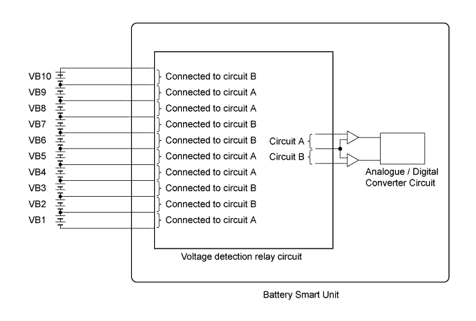
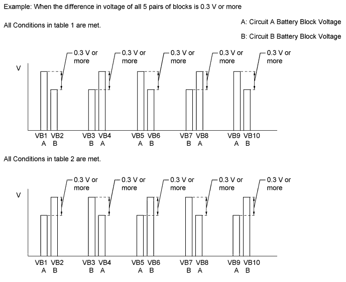
| Result | Proceed to |
| All conditions in table 1 are met. | A |
| All conditions in table 2 are met. | |
| Other than above | B |
Turn the ignition switch off.
|
| ||||
| A | ||
 | ||
| ||
| 3.CHECK DTC OUTPUT (HYBRID CONTROL) |
Connect the Techstream to the DLC3.
Turn the ignition switch to ON (IG).
Enter the following menus: Powertrain / Hybrid Control / Trouble Codes.
Check if DTCs are output.
| Result | Proceed to |
| P3015-123 is output. | A |
| P3015-123 is not output. | B |
Turn the ignition switch off.
|
| ||||
| A | ||
| ||
| ||
