| B |  |
| GO TO DTC CHART (HYBRID BATTERY SYSTEM) (Click here) |
DTC P0B3D-123 Hybrid Battery Voltage Sensor "A" Circuit Low |
DTC P0B42-123 Hybrid Battery Voltage Sensor "B" Circuit Low |
DTC P0B47-123 Hybrid Battery Voltage Sensor "C" Circuit Low |
DTC P0B4C-123 Hybrid Battery Voltage Sensor "D" Circuit Low |
DTC P0B51-123 Hybrid Battery Voltage Sensor "E" Circuit Low |
DTC P0B56-123 Hybrid Battery Voltage Sensor "F" Circuit Low |
DTC P0B5B-123 Hybrid Battery Voltage Sensor "G" Circuit Low |
DTC P0B60-123 Hybrid Battery Voltage Sensor "H" Circuit Low |
DTC P0B65-123 Hybrid Battery Voltage Sensor "I" Circuit Low |
DTC P0B6A-123 Hybrid Battery Voltage Sensor "J" Circuit Low |
DTC P0B6F-123 Hybrid Battery Voltage Sensor "K" Circuit Low |
DTC P308A-123 Hybrid Battery Voltage Sensor All Circuits Low |
| DTC No. | INF Code | DTC Detection Condition | Trouble Area |
| P0B3D P0B42 P0B47 P0B4C P0B51 P0B56 P0B5B P0B60 P0B65 P0B6A P0B6F | 123 | The battery block voltage detection line has a malfunction and any of the battery block voltages become lower than the specified value (open). (1 trip detection logic) |
|
| P308A | The battery block voltage detection line is open (all blocks) or all battery block voltages become lower than the specified value (possibility of open or loosely connected connector). (1 trip detection logic) |
| DTC No. | Data List |
| P0B3D-123 P0B42-123 P0B47-123 P0B4C-123 P0B51-123 P0B56-123 P0B5B-123 P0B60-123 P0B65-123 P0B6A-123 P0B6F-123 | Battery Block Vol -V01 to V10 |
| P308A-123 |
|
| Related DTCs | P0B3D (INF 123) / P0B42 (INF 123) / P0B47 (INF 123) / P0B4C (INF 123) / P0B51 (INF 123) / P0B56 (INF 123) / P0B5B (INF 123) / P0B60 (INF 123) / P0B65 (INF 123) / P0B6A (INF 123) / P0B6F (INF 123) / P308A (INF 123): Battery voltage sensor circuit malfunction (open) |
| Required sensors / components | Battery smart unit |
| Frequency of operation | Continuous |
| Duration | TMC's intellectual property |
| MIL operation | TMC's intellectual property |
| Sequence of operation | None |
| The monitor will run whenever the following DTCs are not present | TMC's intellectual property |
| Other conditions belong to TMC's intellectual property | - |
| TMC's intellectual property | - |
| Battery smart unit | DTC P0B3D (INF 123) / P0B42 (INF 123) / P0B47 (INF 123) / P0B4C (INF 123) / P0B51 (INF 123) / P0B56 (INF 123) / P0B5B (INF 123) / P0B60 (INF 123) / P0B65 (INF 123) / P0B6A (INF 123) / P0B6F (INF 123) / P308A (INF 123) is not detected |
| 1.CHECK DTC OUTPUT (HYBRID CONTROL) |
Connect the Techstream to the DLC3.
Turn the ignition switch to ON (IG).
Enter the following menus: Powertrain / Hybrid Control / Trouble Codes.
Read output DTCs (Click here).
| Result | Proceed to |
| P0AFC-123 or P0A95-123 is not output. | A |
| P0AFC-123 or P0A95-123 is also output. | B |
Turn the ignition switch off.
Disconnect the Techstream from the DLC3.
|
| ||||
| A | |
 |
| 2.CHECK CONNECTOR CONNECTION CONDITION |
Check that the service plug grip is not installed.
Remove the No. 1 hybrid battery shield sub-assembly .
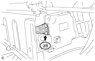 |
Check the connections of the z9 connector of the battery smart unit.
Install the No. 1 hybrid battery shield sub-assembly.
|
| ||||
| OK | |
|
| 3.REPLACE BATTERY SMART UNIT |
| NEXT | |
|
| 4.CLEAR DTC (HV) |
Connect the Techstream to the DLC3.
Turn the ignition switch to ON (IG).
Enter the following menus: Powertrain / Hybrid Control / Trouble Codes.
Clear the DTCs and freeze frame data (Click here).
Turn the ignition switch to ON (IG) and wait for 10 seconds or more.
Disconnect the Techstream from the DLC3.
| NEXT | |
|
| 5.RECONFIRM DTC OUTPUT (HV) |
Connect the Techstream to the DLC3.
Turn the ignition switch to ON (IG).
Enter the following menus: Powertrain / Hybrid Control / Trouble Codes.
Read output DTCs (Click here).
| Result | Proceed to |
| Battery block voltage DTCs for this diagnostic procedure are not output | A |
| Battery block voltage DTCs for this diagnostic procedure are output | B |
Turn the ignition switch off.
Disconnect the Techstream from the DLC3.
|
| ||||
| A | ||
 | ||
| ||