 |
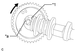
Put the camshaft timing gear assembly and camshaft together with the straight pin and key groove misaligned as shown in the illustration.
| *1 | Straight Pin |
| *a | Key Groove |
CAMSHAFT > INSTALLATION |
| 1. INSTALL CAMSHAFT TIMING GEAR ASSEMBLY |
|
Put the camshaft timing gear assembly and camshaft together with the straight pin and key groove misaligned as shown in the illustration.
| *1 | Straight Pin |
| *a | Key Groove |
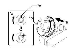 |
Turn the camshaft timing gear assembly as shown in the illustration while pushing it gently against the camshaft. Push further at the position where the pin fits into the groove.
| *a | View A |
| *b | Straight Pin |
| *c | Key Groove |
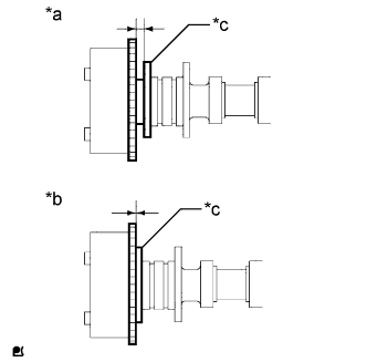 |
Check that there is no clearance between the camshaft timing gear assembly and camshaft flange.
| *a | INCORRECT |
| *b | CORRECT |
| *c | Flange |
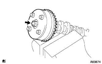 |
Tighten the bolt with the camshaft timing gear assembly secured in place.
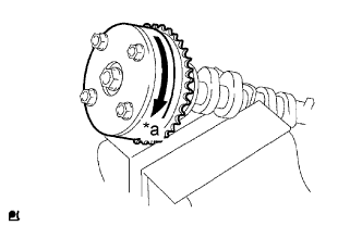 |
Check that the camshaft timing gear assembly can move to the retard direction (clockwise) and is locked in the most retarded position.
| *a | Lock |
| 2. INSTALL CAMSHAFT |
Apply a light coat of engine oil to the camshaft journals and cylinder head sub-assembly journals.
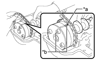 |
Install the chain sub-assembly onto the camshaft timing gear assembly with the paint mark on the chain sub-assembly aligned with the timing mark on the camshaft timing gear assembly as shown in the illustration.
| *a | Paint Mark |
| *b | Timing Mark |
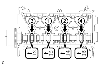 |
Examine the front marks and numbers, and tighten the 4 No. 2 camshaft bearing caps with the 8 bolts in the sequence shown in the illustration.
| 3. INSTALL NO. 2 CAMSHAFT |
Apply a light coat of engine oil to the No. 2 camshaft journals and cylinder head sub-assembly journals.
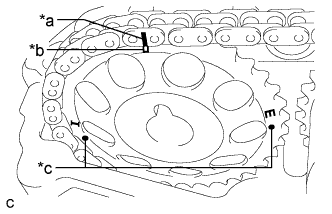 |
Put the camshaft timing gear or sprocket on the cylinder head sub-assembly with the paint mark on the chain sub-assembly aligned with the timing mark on the camshaft timing gear or sprocket.
| *a | Paint Mark |
| *b | Timing Mark (Rectangle) |
| *c | Mark (Circle) |
While holding the No. 2 camshaft by hand, temporarily install the No. 2 camshaft to the camshaft timing gear or sprocket using the bolt.
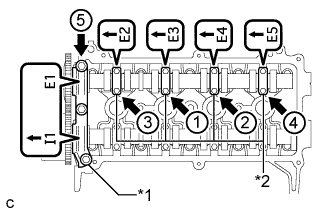 |
Examine the front marks and numbers, and tighten the No. 1 camshaft bearing cap and No. 2 camshaft bearing caps with the 11 bolts in the sequence shown in the illustration.
| *1 | No. 1 Camshaft Bearing Cap |
| *2 | No. 2 Camshaft Bearing Cap |
Using a 14 mm union nut wrench, tighten the bolts onto the camshaft timing gear or sprocket while holding the hexagonal portion of the No. 2 camshaft.
Remove the hexagon wrench from the No. 1 chain tensioner assembly.
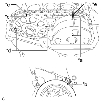 |
Turn the crankshaft damper until its notch and timing mark "0" of the timing chain cover are aligned.
| *a | Timing Mark |
| *b | Timing Notch |
| *c | Timing Mark (Rectangle) |
| *d | Mark (Circle) |
| *e | Paint Mark |
Check that all the pairs of timing marks are aligned.
| 4. INSTALL SCREW PLUG |
Apply a few drops of adhesive to 2 or 3 threads of the screw plug.
Using an 8 mm hexagon socket wrench, install the screw plug.
| 5. INSTALL CYLINDER HEAD COVER SUB-ASSEMBLY |
Install a new gasket to the cylinder head cover sub-assembly.
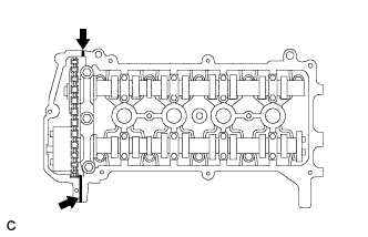 |
Apply seal packing to the 2 locations shown in the illustration.
 | Apply Seal Packing |
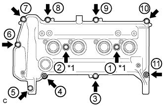 |
Temporarily install the cylinder head cover sub-assembly with the 9 bolts, 2 nuts and 2 new seal washers.
| *1 | Seal Washer |
Using several steps, uniformly tighten the bolts and nuts in the sequence shown in the illustration.
Connect the No. 1 ventilation hose and No. 2 ventilation hose.
| 6. CONNECT ENGINE WIRE |
Install the engine wire with the 3 bolts.
Connect the wire harness clamp.
Connect the 4 injector connectors.
| 7. INSTALL IGNITION COIL ASSEMBLY |
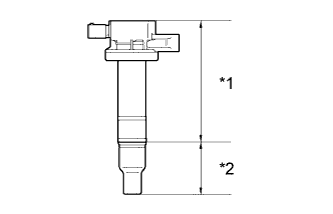 |
Install the 4 No. 1 ignition coils with the 4 bolts.
| *a | Body |
| *b | Cap |
Connect the 4 No. 1 ignition coil connectors.
| 8. INSTALL EGR COOLER ASSEMBLY |