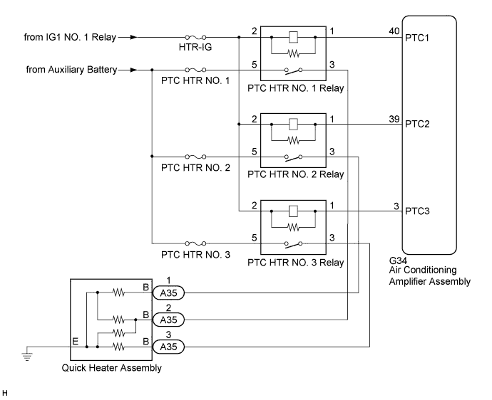
AIR CONDITIONING SYSTEM > PTC Heater Circuit |
| Control ECU | Condition |
| Air Conditioning Amplifier Assembly | Blower motor on |
| Temperature set to MAX HOT | |
| ECO mode switch (eco switch assembly) off | |
| IDH terminal signal less than 1 V (Inverter with converter assembly overload not detected) | |
| Engine coolant temperature approximately 50°C or lower | |
| Ambient temperature 10°C or lower |
| 1.PERFORM ACTIVE TEST USING TECHSTREAM |
Connect the Techstream to the DLC3.
Turn the ignition switch to ON (IG).
Turn the Techstream on.
Enter the following menus: Body Electrical / Air Conditioner / Active Test.
Check the operation by referring to the table below.
| Tester Display | Test Part | Control Range | Diagnostic Note |
| Heater Active Level | Quick heater assembly | Min.: 0, Max.: 3 | - |
|
| ||||
| OK | |
 |
| 2.INSPECT PTC HEATER RELAY |
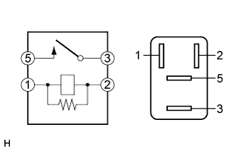 |
Remove the PTC HTR NO. 1 relay, PTC HTR NO. 2 relay and PTC HTR NO. 3 relay.
Measure the resistance according to the value(s) in the table below.
| Tester Connection | Condition | Specified Condition |
| 3 - 5 | Auxiliary battery voltage is not applied between terminals 1 and 2 | 10 kΩ or higher |
| 3 - 5 | Auxiliary battery voltage is applied between terminals 1 and 2 | Below 1 Ω |
|
| ||||
| OK | |
|
| 3.CHECK HARNESS AND CONNECTOR (PTC HEATER RELAY - POWER SOURCE) |
Measure the voltage according to the value(s) in the table below.
| Tester Connection | Condition | Specified Condition |
| 5 - Body ground | Ignition switch off | 11 to 14 V |
| 2 - Body ground | Ignition switch ON (IG) | 11 to 14 V |
| Tester Connection | Condition | Specified Condition |
| 5 - Body ground | Ignition switch off | 11 to 14 V |
| 2 - Body ground | Ignition switch ON (IG) | 11 to 14 V |
| Tester Connection | Condition | Specified Condition |
| 5 - Body ground | Ignition switch off | 11 to 14 V |
| 2 - Body ground | Ignition switch ON (IG) | 11 to 14 V |
|
| ||||
| OK | |
|
| 4.CHECK HARNESS AND CONNECTOR (PTC HEATER RELAY - AIR CONDITIONING AMPLIFIER ASSEMBLY) |
Disconnect the G34 air conditioning amplifier assembly connector.
Measure the resistance according to the value(s) in the table below.
| Tester Connection | Condition | Specified Condition |
| 1 - G34-40 (PTC1) | Always | Below 1 Ω |
| 1 - Body ground | Always | 10 kΩ or higher |
| Tester Connection | Condition | Specified Condition |
| 1 - G34-39 (PTC2) | Always | Below 1 Ω |
| 1 - Body ground | Always | 10 kΩ or higher |
| Tester Connection | Condition | Specified Condition |
| 1 - G34-3 (PTC3) | Always | Below 1 Ω |
| 1 - Body ground | Always | 10 kΩ or higher |
|
| ||||
| OK | |
|
| 5.CHECK HARNESS AND CONNECTOR (PTC HEATER RELAY - QUICK HEATER ASSEMBLY) |
Disconnect the A35 quick heater assembly connector.
Measure the resistance according to the value(s) in the table below.
| Tester Connection | Condition | Specified Condition |
| 3 - A35-2 (B) | Always | Below 1 Ω |
| 3 - Body ground | Always | 10 kΩ or higher |
| Tester Connection | Condition | Specified Condition |
| 3 - A35-1 (B) | Always | Below 1 Ω |
| 3 - Body ground | Always | 10 kΩ or higher |
| Tester Connection | Condition | Specified Condition |
| 3 - A35-3 (B) | Always | Below 1 Ω |
| 3 - Body ground | Always | 10 kΩ or higher |
|
| ||||
| OK | |
|
| 6.INSPECT QUICK HEATER ASSEMBLY |
Remove the quick heater assembly (Click here).
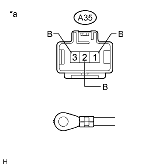 |
Measure the resistance according to the value(s) in the table below.
| Tester Connection | Condition | Specified Condition |
| A35-1 (B)- Ground terminal | Always | Below 1 Ω |
| A35-2 (B)- Ground terminal | Always | Below 1 Ω |
| A35-3 (B)- Ground terminal | Always | Below 1 Ω |
| *a | Component without harness connected (Quick Heater Assembly) |
|
| ||||
| OK | ||
 | ||
| ||
