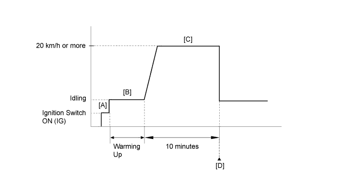
DTC P0403 Exhaust Gas Recirculation Control Circuit |
| DTC No. | DTC Detection Condition | Trouble Area |
| P0403 | Open or short in EGR valve circuit (1 trip detection logic). |
|
| Related DTCs | P0403: EGR valve circuit range check |
| Required Sensors/Components (Main) | EGR valve assembly |
| Required Sensors/Components (Related) | - |
| Frequency of Operation | Continuous |
| Duration | - |
| MIL Operation | Immediate |
| Sequence of Operation | None |
| Monitor runs whenever the following DTCs are not stored | None |
| All of the following conditions are met | - |
| Engine | Running |
| Auxiliary battery voltage | 10.5 V or higher |
| Time after ignition switch off to ON (IG) | More than 0.5 seconds |
| One of the following conditions is met | Conditions A, B, C or D |
| A. All of the following conditions are met | - |
| EGR1 output terminal voltage | Low |
| Either of the following conditions is met | 1 or 2 |
| 1. Step motor | Driving |
| 2. EGR1 | Not operating |
| B. All of the following conditions are met | - |
| EGR2 output terminal voltage | Low |
| Either of the following conditions is met | 3 or 4 |
| 3. Step motor | Driving |
| 4. EGR2 | Not operating |
| C. All of the following conditions are met | - |
| EGR3 output terminal voltage | Low |
| Either of the following conditions is met | 5 or 6 |
| 5. Step motor | Driving |
| 6. EGR3 | Not operating |
| D. All of the following conditions are met | - |
| EGR4 output terminal voltage | Low |
| Either of the following conditions is met | 7 or 8 |
| 7. Step motor | Driving |
| 8. EGR4 | Not operating |
| Techstream Display | Description |
| NORMAL |
|
| ABNORMAL |
|
| INCOMPLETE |
|
| N/A |
|
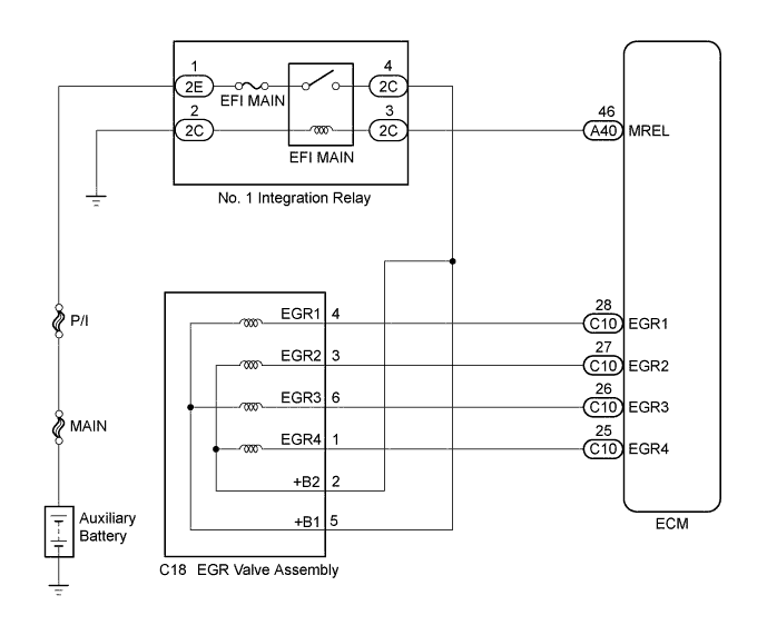
| 1.PERFORM ACTIVE TEST USING TECHSTREAM (CONTROL THE EGR STEP POSITION) |
Connect the Techstream to the DLC3.
Turn the ignition switch to ON (IG).
Turn the Techstream on.
Put the engine in inspection mode (maintenance mode) (Click here).
Start the engine and warm it up until the engine coolant temperature reaches 75°C (167°F) or higher.
Enter the following menus: Powertrain / Engine and ECT / Active Test / Control the EGR Step Position / Primary / Throttle Idle Position and MAP.
Confirm that the Throttle Idle Position is ON and check the engine idling condition and MAP values in the Data List while performing the Active Test.
| - | EGR Step Position (Active Test) | |
| 0 Steps | 0 to 30 Steps | |
| Idling condition (Throttle Idle Position: ON) | Steady idling | Idling changes from steady to rough idling or engine stalls |
| MAP (Data List) | MAP value is 20 to 40 kPa(abs) [150 to 300 mmHg(abs)] (EGR valve is fully closed) | MAP value is at least +10 kPa (75 mmHg) higher than when EGR valve is fully closed |
|
| ||||
| OK | ||
 | ||
| ||
| 2.INSPECT EGR VALVE ASSEMBLY |
Inspect the EGR valve assembly (Click here).
|
| ||||
| OK | |
 |
| 3.CHECK TERMINAL VOLTAGE (POWER SOURCE OF EGR VALVE ASSEMBLY) |
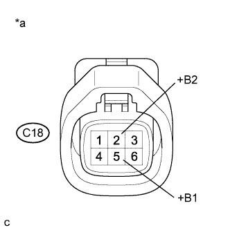 |
Disconnect the EGR valve assembly connector.
Turn the ignition switch to ON (IG).
Measure the voltage according to the value(s) in the table below.
| Tester Connection | Condition | Specified Condition |
| C18-5 (+B1) - Body ground | Ignition switch ON (IG) | 11 to 14 V |
| C18-2 (+B2) - Body ground | Ignition switch ON (IG) | 11 to 14 V |
| *a | Front view of wire harness connector (to EGR Valve Assembly) |
|
| ||||
| OK | |
|
| 4.CHECK HARNESS AND CONNECTOR (EGR VALVE ASSEMBLY - ECM) |
Disconnect the EGR valve assembly connector.
Disconnect the ECM connector.
Measure the resistance according to the value(s) in the table below.
| Tester Connection | Condition | Specified Condition |
| C18-4 (EGR1) - C10-28 (EGR1) | Always | Below 1 Ω |
| C18-3 (EGR2) - C10-27 (EGR2) | Always | Below 1 Ω |
| C18-6 (EGR3) - C10-26 (EGR3) | Always | Below 1 Ω |
| C18-1 (EGR4) - C10-25 (EGR4) | Always | Below 1 Ω |
| C18-4 (EGR1) or C10-28 (EGR1) - Body ground | Always | 10 kΩ or higher |
| C18-3 (EGR2) or C10-27 (EGR2) - Body ground | Always | 10 kΩ or higher |
| C18-6 (EGR3) or C10-26 (EGR3) - Body ground | Always | 10 kΩ or higher |
| C18-1 (EGR4) or C10-25 (EGR4) - Body ground | Always | 10 kΩ or higher |
|
| ||||
| OK | ||
| ||
| ||
| 5.CHECK HARNESS AND CONNECTOR (EGR VALVE ASSEMBLY - NO. 1 INTEGRATION RELAY) |
Disconnect the EGR valve assembly connector.
Remove the No. 1 integration relay from the No. 2 engine room relay block and No. 2 junction block assembly.
Measure the resistance according to the value(s) in the table below.
| Tester Connection | Condition | Specified Condition |
| C18-5 (+B1) - 2C-4 | Always | Below 1 Ω |
| C18-2 (+B2) - 2C-4 | Always | Below 1 Ω |
| C18-5 (+B1) or 2C-4 - Body ground | Always | 10 kΩ or higher |
| C18-2 (+B2) or 2C-4 - Body ground | Always | 10 kΩ or higher |
|
| ||||
| OK | ||
| ||
| ||

