 |
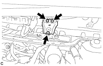
Remove the 3 bolts and inner cowl top to cowl brace.
COOLER EXPANSION VALVE > REMOVAL |
| 1. RECOVER REFRIGERANT FROM AIR CONDITIONING SYSTEM |
Start the hybrid system.
Operate the cooler compressor under the conditions show below:
| Item | Condition |
| Engine Speed | Idling |
| Operating Time | 3 minutes or more |
| A/C Switch Status | ON |
| Blower Switch Status | HI |
| Set Temperature | MAX COOL |
Stop the engine.
Recover the refrigerant from the A/C system using a refrigerant recovery unit.
| 2. REMOVE WINDSHIELD WIPER MOTOR AND LINK ASSEMBLY |
| 3. REMOVE INNER COWL TOP TO COWL BRACE |
|
Remove the 3 bolts and inner cowl top to cowl brace.
| 4. REMOVE FRONT AIR SHUTTER SEAL |
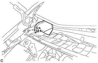 |
Disengage the clamp to remove the front air shutter seal.
| 5. REMOVE FRONT NO. 1 VENTILATOR SEAL |
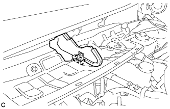 |
Disengage the clamp to remove the front No. 1 ventilator seal.
| 6. REMOVE OUTER COWL TOP PANEL SUB-ASSEMBLY |
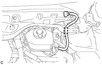 |
Disengage the clamp to separate the wire harness from the outer cowl top panel sub-assembly.
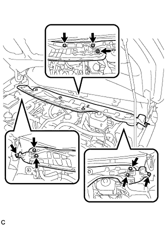 |
Remove the 8 bolts, nut and outer cowl top panel sub-assembly.
| 7. DISCONNECT SUCTION PIPE SUB-ASSEMBLY |
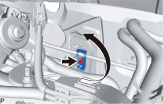 |
Remove the bolt and rotate the hook connector.
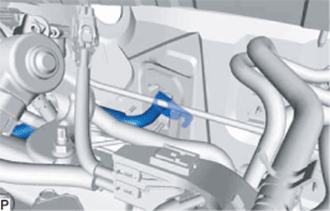 |
Disconnect the suction pipe sub-assembly.
Remove the O-ring from the suction pipe sub-assembly.
| 8. DISCONNECT LIQUID PIPE SUB-ASSEMBLY |
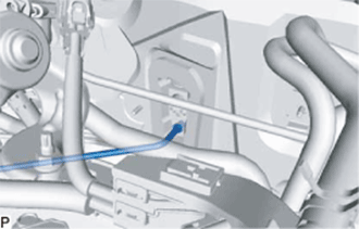 |
Disconnect the liquid pipe sub-assembly.
Remove the O-ring from the liquid pipe sub-assembly.
| 9. REMOVE COOLER EXPANSION VALVE |
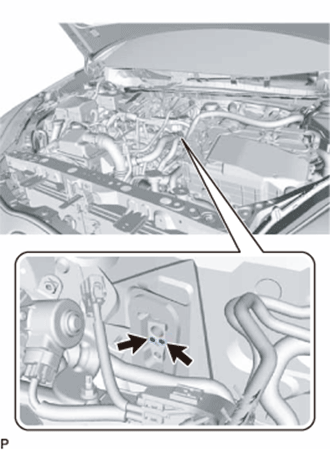 |
Using a 4 mm hexagon wrench, remove the 2 hexagon bolts.
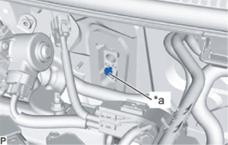 |
Temporarily install the bolt for the suction pipe sub-assembly halfway to the cooler expansion valve.
| *a | Bolt for Suction Pipe Sub-assembly |
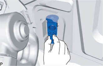 |
Hold the bolt and pull it to remove the cooler expansion valve as shown in the illustration.
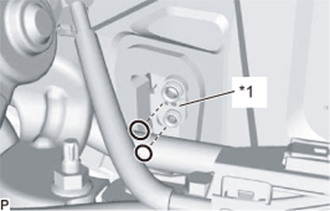 |
Remove the 2 O-rings from the No. 1 cooler evaporator sub-assembly.
| *1 | No. 1 Cooler Evaporator Sub-assembly |