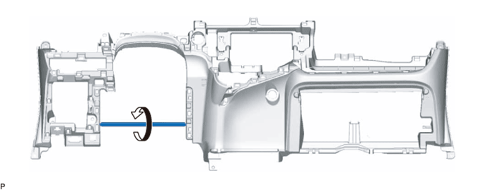
When using a new lower instrument panel subassembly:
Immediately before installing the lower instrument panel sub-assembly, twist and cut off the portion shown in the illustration.
LOWER INSTRUMENT PANEL > INSTALLATION |
| 1. INSTALL LOWER INSTRUMENT PANEL SUB-ASSEMBLY |
When using a new lower instrument panel subassembly:
Immediately before installing the lower instrument panel sub-assembly, twist and cut off the portion shown in the illustration.
Install the lower instrument panel sub-assembly with the 2 bolts <A>, 7 screws <C> and screw <B>.
Engage the 2 claws to connect the DLC3.
Connect each connector.
Engage each clamp.
| 2. CONNECT HOOD LOCK CONTROL LEVER SUB-ASSEMBLY |
Engage the claw and 2 guides to connect the hood lock control lever sub-assembly.
| 3. INSTALL COWL SIDE TRIM BOARD RH |
| 4. INSTALL FRONT DOOR SCUFF PLATE RH |
| 5. INSTALL COWL SIDE TRIM BOARD LH |
Engage the clip.
Install the cowl side trim board with the clip.
| 6. INSTALL FRONT DOOR SCUFF PLATE LH |
Engage the 8 claws to install the front door scuff plate.
| 7. INSTALL GLOVE COMPARTMENT DOOR ASSEMBLY |
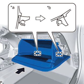 |
With the glove compartment door assembly opened approximately 55° from its closed position, engage the 2 hinges horizontally.
| *a | Opened approximately 55° |
| *b | Closed |
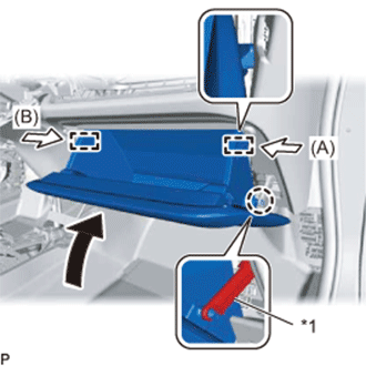 |
Slightly bend the stoppers (A) and (B) in the directions indicated by the arrows in the illustration and engage the stoppers to install the glove compartment door assembly.
| *1 | Glove Compartment Door Stopper Sub-assembly |
Engage the claw and connect the glove compartment door stopper sub-assembly.
| 8. INSTALL INSTRUMENT PANEL BOX ASSEMBLY |
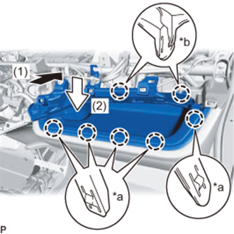 |
Push the instrument panel box assembly in the direction indicated by the arrow (1) to engage the 2 claws (B) as shown in the illustration.
| *a | Claw (A) |
| *b | Claw (B) |
Push the instrument panel box assembly in the direction indicated by the arrow (2) to engage the 5 claws (A) as shown in the illustration.
Install the instrument panel box assembly with the screw.
Engage the 3 clamps.
| 9. INSTALL REAR CONSOLE BOX ASSEMBLY (w/o Console Box Lid) |
Engage the 2 clips.
Install the rear console box assembly with the bolt and 2 screws.
| 10. INSTALL CONSOLE BOX CARPET (w/o Console Box Lid) |
Install the console box carpet.
| 11. INSTALL REAR CONSOLE BOX ASSEMBLY (w/ Console Box Lid) |
Engage the 2 clips.
Install the rear console box assembly with the 3 bolts and 2 screws.
| 12. INSTALL CONSOLE BOX PLATE (w/ Console Box Lid) |
Install the console box plate.
| 13. INSTALL FRONT CONSOLE BOX |
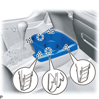 |
Engage the 2 claws and 4 clips to install the front console box.
| 14. INSTALL UPPER CONSOLE PANEL |
Engage the 2 claws and 6 clips to install the upper console panel.
| 15. INSTALL REAR CONSOLE BOX COVER |
Connect each connector.
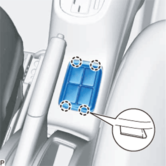 |
Engage the 4 claws to install the rear console box cover.
| 16. INSTALL ROOM TEMPERATURE SENSOR (COOLER THERMISTOR) |
Connect the connector and aspirator.
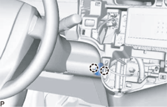 |
Engage the 2 claws to install the room temperature sensor (cooler thermistor).
| 17. INSTALL AIR CONDITIONING CONTROL ASSEMBLY |
Connect the connector.
Engage the 4 clips to install the air conditioning control assembly.
| 18. INSTALL LOWER INSTRUMENT CLUSTER FINISH PANEL GARNISH |
Engage the 3 claws, 8 clips and 3 guides to install the lower instrument cluster finish panel garnish.
| 19. INSTALL RADIO TUNER OPENING COVER WITH BRACKET (w/o Radio Receiver) |
Install the radio tuner opening cover with bracket with the 4 screws.
| 20. INSTALL RADIO RECEIVER ASSEMBLY WITH BRACKET (for Radio Receiver Type) |
Connect each connector.
Engage the 2 guides to the vehicle body to temporarily install the radio receiver assembly with bracket.
Install the radio receiver assembly with bracket with the 4 screws.
| 21. INSTALL RADIO AND DISPLAY RECEIVER ASSEMBLY WITH BRACKET (for Radio and Display Type) |
Connect each connector.
Engage the 2 guides to the vehicle body to temporarily install the radio and display receiver assembly with bracket.
Install the radio and display receiver assembly with bracket with the 4 screws.
| 22. INSTALL NO. 6 HEATER TO REGISTER DUCT ASSEMBLY |
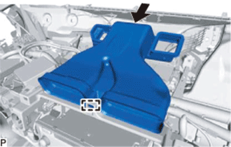 |
Engage the guide as shown in the illustration.
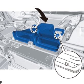 |
Engage the 2 claws as shown in the illustration.
Engage the clamp to install the No. 6 heater to register duct assembly.
| 23. INSTALL LOWER NO. 1 INSTRUMENT PANEL AIRBAG ASSEMBLY |
Check that the ignition switch is off.
Check that the cable is disconnected from the negative (-) auxiliary battery terminal.
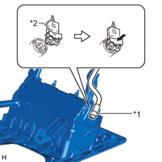 |
Connect the airbag connector to the lower No. 1 instrument panel airbag assembly.
| *1 | Airbag Connector |
| *2 | Airbag Connector Lock |
Push in the airbag connector lock to install the airbag connector.
Temporarily install the lower No. 1 instrument panel airbag assembly with the 7 claws and the 3 guides.
Install the 4 bolts.
| 24. INSTALL LOWER STEERING COLUMN COVER |
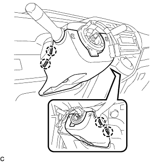 |
Engage the 4 claws to install the lower steering column cover.
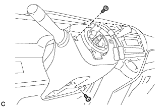 |
Install the 3 screws.
| 25. INSTALL LOWER INSTRUMENT PANEL FINISH PANEL LH |
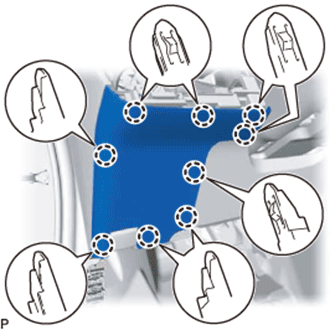 |
Engage the 9 claws to install the lower instrument panel finish panel LH as shown in the illustration.
| 26. INSTALL NO. 1 SWITCH HOLE BASE |
Connect each connector.
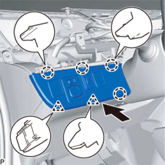 |
Engage the 4 claws and 2 clips to install the No. 1 switch hole base.
| 27. INSTALL UPPER INSTRUMENT PANEL ASSEMBLY |