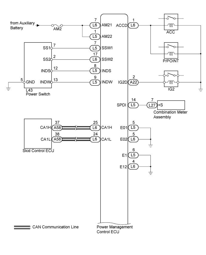
ENTRY AND START SYSTEM (for Start Function) > Power Source Mode does not Change to ON (READY) |
| 1.CHECK HYBRID SYSTEM READY ON |
Place the electrical key on the driver seat.
Depress the brake pedal.
Check that the power switch indicator light is green. Then press the power switch to check if the hybrid system turns on (READY).
|
| ||||
| OK | ||
 | ||
| ||
| 2.CHECK FOR DTC |
Turn the power switch off.
Connect the intelligent tester to the DLC3.
Turn the power switch on (IG).
Turn the intelligent tester on.
Enter the following menus: Powertrain / Hybrid Control / DTC.
Check for DTCs.
|
| ||||
| OK | |
 |
| 3.CHECK FOR DTC |
Enter the following menus: Body / Power Source Control / Data List.
Check for DTCs.
|
| ||||
| OK | |
|
| 4.CHECK POWER SOURCE CONDITION |
Check the power source mode change.
When the key is inside the vehicle and the park (P) is selected, check that pressing the power switch causes the power source mode to change.
| Result | Proceed to |
| off → on (ACC) → on (IG) → off | A |
| Power source mode does not change to on (IG and ACC) | B |
| Power source mode does not change to on (IG) | C |
| Power source mode does not change to on (ACC) | D |
|
| ||||
|
| ||||
|
| ||||
| A | |
|
| 5.READ VALUE USING INTELLIGENT TESTER (STOP LIGHT SWITCH ASSEMBLY) |
Read the Data List according to the display on the intelligent tester.
| Tester Display | Measurement Item/Range | Normal Condition | Diagnostic Note |
| Stop Light Switch1 | Stop light switch 1/ON or OFF | ON: Brake pedal depressed OFF: Brake pedal released | - |
|
| ||||
| OK | |
|
| 6.READ VALUE USING INTELLIGENT TESTER (L CODE) |
Enter the following menus: Body / Entry & Start / Data List.
Read the Data List according to the display on the intelligent tester.
| Tester Display | Measurement Item/Range | Normal Condition | Diagnostic Note |
| L Code Check | L code certification result/OK or NG | OK: L code certification result normal NG: L code certification result abnormal | - |
|
| ||||
| OK | |
|
| 7.READ VALUE USING INTELLIGENT TESTER (ENGINE START REQUEST) |
Read the Data List according to the display on the intelligent tester.
| Tester Display | Measurement Item/Range | Normal Condition | Diagnostic Note |
| Engine Start Request | Start request signal response/OK or NG | OK: Start request condition signal received NG: Start request condition signal not received | - |
| Result | Proceed to |
| OK (w/ Airbag Cut-off Switch) | A |
| OK (w/o Airbag Cut-off Switch) | B |
| NG | B |
|
| ||||
| A | |
|
| 8.READ VALUE USING INTELLIGENT TESTER (S CODE) |
Read the Data List according to the display on the intelligent tester.
| Tester Display | Measurement Item/Range | Normal Condition | Diagnostic Note |
| S Code Check | S code certification result/OK or NG | OK: S code certification result normal NG: S code certification result abnormal | - |
|
| ||||
| OK | |
|
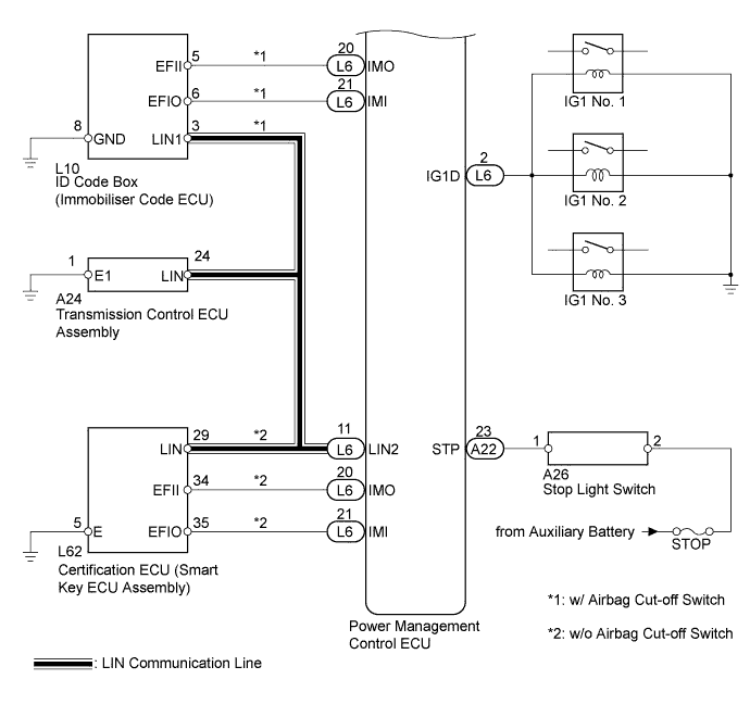
| 9.CHECK ID CODE BOX (IMMOBILISER CODE ECU) |
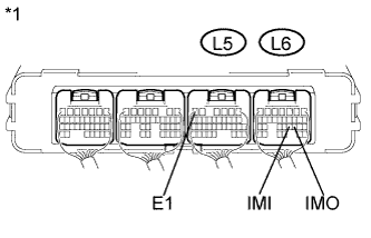 |
Measure the voltage according to the value(s) in the table below.
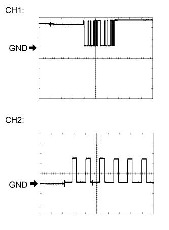 |
Waveform 1
| Tester Connection | L6-20 (IMO) - L5-6 (E1) |
| Tool Setting | 5 V/DIV., 500 ms./DIV. |
| Vehicle Condition | Within 3 seconds after power switch on (READY), or within 3 seconds after power switch first turned on (IG) after battery disconnected and connected |
Waveform 2
| Tester Connection | L6-21 (IMI) - L5-6 (E1) |
| Tool Setting | 5 V/DIV., 50 ms./DIV. |
| Vehicle Condition | Power switch on (IG) |
| *1 | Component with harness connected (Power Management Control ECU) |
|
| ||||
| OK | |
|
| 10.READ VALUE USING INTELLIGENT TESTER |
Enter the following menus: Body / Power Source Control / Data List.
Read the Data List according to the display on the intelligent tester.
| Tester Display | Measurement Item/Range | Normal Condition | Diagnostic Note |
| Starter Request Signal | Hybrid control system start request signal / ON or OFF | ON: STSW signal is on OFF: STSW signal is off | - |
|
| ||||
| OK | ||
| ||
| ||
| 11.INSPECT STOP LIGHT SWITCH ASSEMBLY |
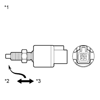 |
Remove the stop light switch assembly (Click here).
Measure the resistance according to the value(s) in the table below.
| Tester Connection | Condition | Specified Condition |
| 1 - 2 | Pushed | 10 kΩ or higher |
| 3 - 4 | Pushed | Below 1 Ω |
| 1 - 2 | Not pushed | Below 1 Ω |
| 3 - 4 | Not pushed | 10 kΩ or higher |
| *1 | Component without harness connected (Stop Light Switch Assembly) |
| *2 | Free |
| *3 | Pushed in |
|
| ||||
| OK | |
|
| 12.CHECK HARNESS AND CONNECTOR (POWER MANAGEMENT CONTROL ECU - STOP LIGHT SWITCH ASSEMBLY) |
Disconnect the A22 connector from the power management control ECU.
Measure the resistance according to the value(s) in the table below.
| Tester Connection | Condition | Specified Condition |
| A22-23 (STP) - A26-1 | Always | Below 1 Ω |
| A22-23 (STP)- Body ground | Always | 10 kΩ or higher |
|
| ||||
| OK | ||
| ||
| ||
| 13.REPLACE TRANSMISSION CONTROL ECU ASSEMBLY |
Replace transmission control ECU assembly (Click here).
| NEXT | |
|
| 14.CHECK HYBRID SYSTEM READY ON |
Place the electrical key on the driver seat.
Depress the brake pedal.
Check that the power switch indicator light is green. Then press the power switch to check if the hybrid system turns on (READY).
| Result | Proceed to |
| OK | A |
| NG (w/ Airbag Cut-off Switch) | B |
| NG (w/o Airbag Cut-off Switch) | C |
|
| ||||
|
| ||||
| A | ||
| ||
| ||
| 15.REPLACE CERTIFICATION ECU (SMART KEY ECU ASSEMBLY) |
Replace certification ECU (Entry & Start ECU assembly).
| NEXT | |
|
| 16.CHECK HYBRID SYSTEM READY ON |
Place the electrical key on the driver seat.
Depress the brake pedal.
Check that the power switch indicator light is green. Then press the power switch to check if the hybrid system turns on (READY).
|
| ||||
| OK | ||
| ||
| ||

