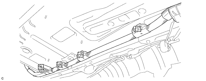
 |
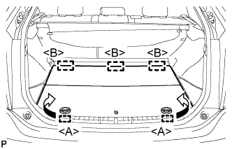
Disengage the 2 guides <A> as shown in the illustration.
FRAME WIRE > REMOVAL |
| 1. PRECAUTION |
| 2. REMOVE REAR NO. 2 FLOOR BOARD |
|
Disengage the 2 guides <A> as shown in the illustration.
Disengage the 3 guides <B> and remove the rear No. 2 floor board.
| 3. REMOVE REAR DECK FLOOR BOX |
Remove the rear deck floor box.
| 4. REMOVE REAR NO. 3 FLOOR BOARD |
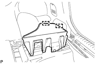 |
Disengage the 2 guides and remove the rear No. 3 floor board.
| 5. DISCONNECT CABLE FROM NEGATIVE BATTERY TERMINAL |
| 6. REMOVE SERVICE PLUG GRIP |
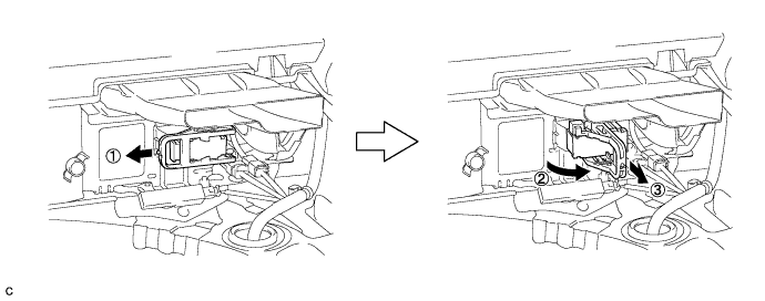
Wear insulating gloves and remove the service plug grip after sliding up the lever of the service plug grip as shown in the illustration.
| 7. REMOVE INVERTER WITH CONVERTER ASSEMBLY |
| 8. REMOVE FRONT EXHAUST PIPE ASSEMBLY |
| 9. REMOVE FRONT NO. 1 FLOOR HEAT INSULATOR |
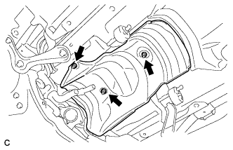 |
Remove the 3 nuts and front No. 1 floor heat insulator.
| 10. REMOVE FRONT FLOOR COVER RH |
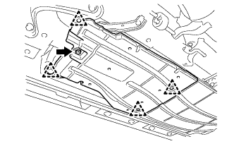 |
Remove the bolt.
Remove the 4 clips and the front floor cover RH.
| 11. REMOVE FRONT CENTER FLOOR COVER RH |
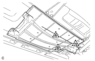 |
Remove the 3 clips and the front floor cover center RH.
| 12. REMOVE FRONT SUSPENSION MEMBER BRACE REAR RH |
Using a transmission jack, hold the front suspension cross member.
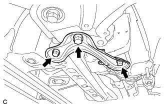 |
Remove the 3 bolts and front suspension member brace rear RH.
| 13. REMOVE REAR SEAT CUSHION ASSEMBLY |
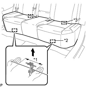 |
Disengage the 2 front hooks of the seat cushion from the vehicle body as shown in the illustration.
| *1 | 100 mm (3.94 in.) or less |
| *2 | Hook |
| *3 | Guide |
Choose a hook to detach first. Place your hands near the hook as shown in the illustration. Then lift the seat cushion to detach the hook.
Repeat the above procedure for the other hook.
Disengage the 2 guides of the seat cushion from the seatback.
Remove the rear seat cushion assembly.
| 14. REMOVE REAR NO. 1 FLOOR BOARD SUB-ASSEMBLY |
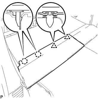 |
Disengage the 2 claws and 2 clips, and remove the rear No. 1 floor board sub-assembly.
| 15. REMOVE REAR NO. 2 FLOOR BOARD SUB-ASSEMBLY |
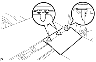 |
Disengage the claw and 2 clips, and remove the rear No. 2 floor board sub-assembly.
| 16. REMOVE REAR NO. 1 FLOOR BOARD |
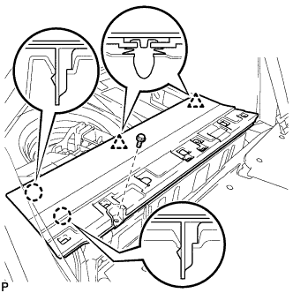 |
Remove the bolt.
Disengage the 2 claws and 2 clips, and remove the rear No. 1 floor board.
| 17. REMOVE REAR FLOOR BOARD SPACER |
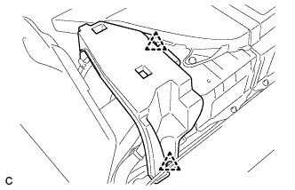 |
Remove the 2 clips and rear floor board spacer.
| 18. REMOVE NO. 1 HYBRID BATTERY EXHAUST DUCT |
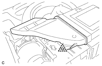 |
Remove the clip and No. 1 hybrid battery exhaust duct.
| 19. REMOVE UPPER HYBRID BATTERY COVER SUB-ASSEMBLY |
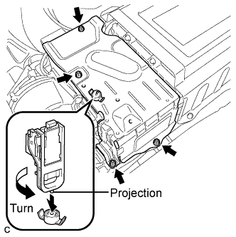 |
Using the service plug grip, remove the battery cover lock striker.
Remove the 4 nuts and upper hybrid battery cover sub-assembly.
| 20. DISCONNECT CABLE FROM BATTERY TERMINAL |
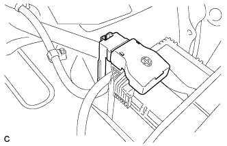 |
Remove the connector cover.
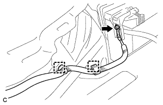 |
Disconnect the 2 clamps, and remove the nut.
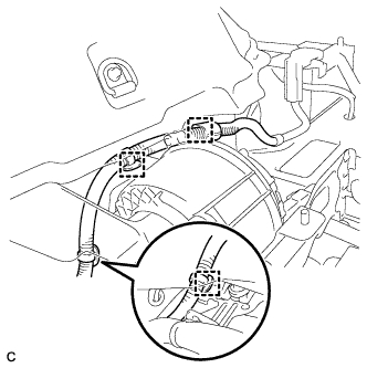 |
Disconnect the 3 wire harness clamps.
| 21. DISCONNECT HYBRID BATTERY JUNCTION BLOCK |
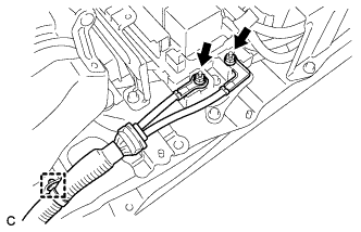 |
Remove the 2 nuts, then disconnect the frame wire from the hybrid battery junction block.
Disconnect the clamp and frame wire.
| 22. REMOVE FRAME WIRE |
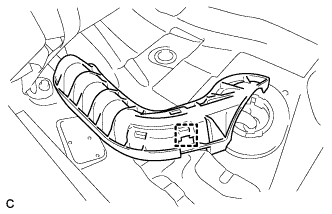 |
Remove the wire harness protector and disconnect the clamp from the floor panel.
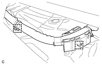 |
Disconnect the 2 wire harness clamps from the floor panel.
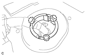 |
Disconnect the 3 claws and push the frame wire out from the floor panel.
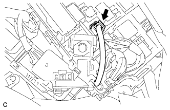 |
Disconnect the connector from the engine room junction block assembly.
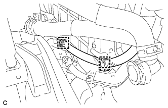 |
Disconnect the 2 clamps shown in the illustration.
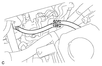 |
Disconnect the clamp shown in the illustration.
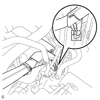 |
Disconnect the clamp shown in the illustration.
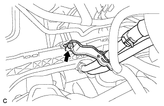 |
Remove the nut and heater water pipe sub-assembly.
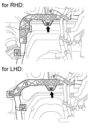 |
Remove the nut and 2 clamps shown in the illustration.
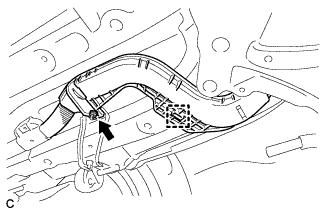 |
Remove the nut and clamp shown in the illustration.
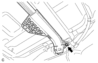 |
Remove the nut shown in the illustration.
Remove the frame wire and the 4 clamps.