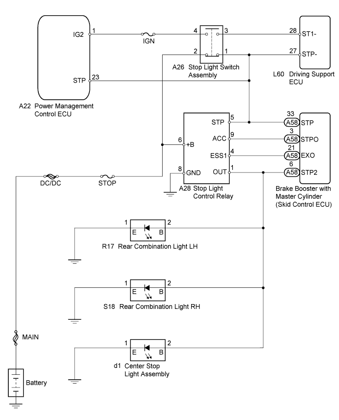
DTC C1A05 Stop Light Switch Circuit |
| DTC No. | DTC Detection Condition | Trouble Area |
| C1A05 | Voltages of terminals ST1- and STP- of driving support ECU are both below 1 V for 1 second |
|
| 1.CHECK HARNESS AND CONNECTOR (STOP LIGHT SWITCH ASSEMBLY - POWER SOURCE) |
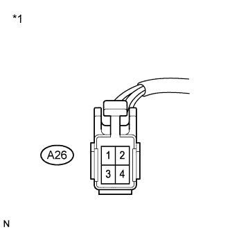 |
Disconnect the stop light switch assembly connector.
Measure the voltage according to the value(s) in the table below.
| Tester Connection | Condition | Specified Condition |
| A26-2 - Body ground | Always | 11 to 14 V |
| *1 | Front view of wire harness connector (to Stop Light Switch Assembly) |
Reconnect the stop light switch assembly connector.
|
| ||||
| OK | |
 |
| 2.CHECK HARNESS AND CONNECTOR (STOP LIGHT SWITCH ASSEMBLY - POWER SOURCE) |
|
Disconnect the stop light switch assembly connector.
Turn the power switch on (IG).
Measure the voltage according to the value(s) in the table below.
| Tester Connection | Condition | Specified Condition |
| A26-4 - Body ground | Power switch on (IG) | 11 to 14 V |
| *1 | Front view of wire harness connector (to Stop Light Switch Assembly) |
Reconnect the stop light switch assembly connector.
|
| ||||
| OK | |
|
| 3.INSPECT STOP LIGHT SWITCH ASSEMBLY |
 |
Remove the stop light switch assembly (Click here).
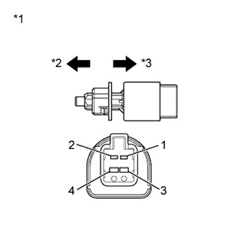
Measure the resistance according to the value(s) in the table below.
| Tester Connection | Switch Condition | Specified Condition |
| 1 - 2 | Switch pin not pushed | Below 1 Ω |
| 3 - 4 | Switch pin not pushed | 10 kΩ or higher |
| 1 - 2 | Switch pin pushed | 10 kΩ or higher |
| 3 - 4 | Switch pin pushed | Below 1 Ω |
| *1 | Component without harness connected (Stop Light Switch Assembly) |
| *2 | Not pushed |
| *3 | Pushed |
Install the stop light switch assembly (Click here).
|
| ||||
| OK | |
|
| 4.CHECK HARNESS AND CONNECTOR (STOP LIGHT SWITCH ASSEMBLY - DRIVING SUPPORT ECU) |
 |
Disconnect the stop light switch assembly connector.
Disconnect the driving support ECU connector.
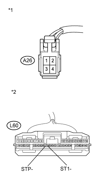
Measure the resistance according to the value(s) in the table below.
| Tester Connection | Switch Condition | Specified Condition |
| A26-3 - L60-28 (ST1-) | Always | Below 1 Ω |
| A26-1 - L60-27 (STP-) | Always | Below 1 Ω |
| Tester Connection | Switch Condition | Specified Condition |
| A26-3 or L60-28 (ST1-) - Body ground | Always | 10 kΩ or higher |
| A26-1 or L60-27 (STP-) - Body ground | Always | 10 kΩ or higher |
| *1 | Front view of wire harness connector (to Stop Light Switch Assembly) |
| *2 | Front view of wire harness connector (to Driving Support ECU) |
Reconnect the stop light switch assembly connector.
Reconnect the driving support ECU connector.
|
| ||||
| OK | |
|
| 5.CHECK HARNESS AND CONNECTOR |
Disconnect the stop light switch assembly connector.
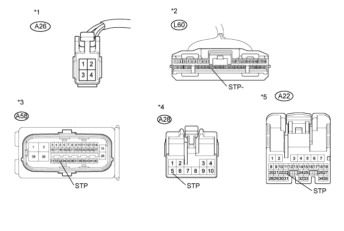
Disconnect the driving support ECU connector.
Disconnect the stop light control relay connector.
Disconnect the brake booster with master cylinder (skid control ECU) connector.
Disconnect the power management control ECU connector.
Measure the resistance according to the value(s) in the table below.
| Tester Connection | Switch Condition | Specified Condition |
| A26-1 or L60-27 (STP-) - Body ground | Always | 10 kΩ or higher |
| A26-1 or A58-33 (STP) - Body ground | Always | 10 kΩ or higher |
| A26-1 or A28-5 (STP) - Body ground | Always | 10 kΩ or higher |
| A26-1 or A22-23 (STP) - Body ground | Always | 10 kΩ or higher |
| *1 | Front view of wire harness connector (to Stop Light Switch Assembly) | *2 | Front view of wire harness connector (to Driving Support ECU) |
| *3 | Front view of wire harness connector (to Brake Booster with Master Cylinder (Skid Control ECU)) | *4 | Front view of wire harness connector (to Stop Light Control Relay) |
| *5 | Front view of wire harness connector (to Power Management Control ECU) | - | - |
Reconnect the stop light switch assembly connector.
Reconnect the driving support ECU connector.
Reconnect the power management control ECU connector.
Reconnect the stop light control relay connector.
Reconnect the brake booster with master cylinder (skid control ECU) connector.
|
| ||||
| OK | ||
 | ||
| ||
| 6.CHECK HARNESS AND CONNECTOR (STOP LIGHT SWITCH ASSEMBLY - STOP LIGHT CONTROL RELAY) |
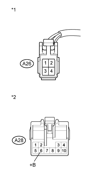 |
Disconnect the stop light switch assembly connector.
Disconnect the stop light control relay connector.
Measure the resistance according to the value(s) in the table below.
| Tester Connection | Switch Condition | Specified Condition |
| A26-2 or A28-6 (+B) - Body ground | Always | 10 kΩ or higher |
| *1 | Front view of wire harness connector (to Stop Light Switch Assembly) |
| *2 | Front view of wire harness connector (to Stop Light Control Relay) |
Reconnect the stop light switch assembly connector.
Reconnect the stop light control relay connector.
|
| ||||
| OK | ||
| ||
| ||

