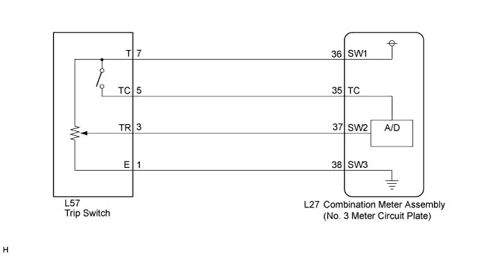
METER / GAUGE SYSTEM > Operating Light Control Rheostat does not Change Light Brightness |
| 1.READ VALUE USING INTELLIGENT TESTER (LIGHT CONTROL DOWN SW, LIGHT CONTROL UP SW) |
Connect the intelligent tester to the DLC3.
Turn the power switch on (IG).
Turn the intelligent tester on.
Enter the following menus: Body / Combination Meter / Data List.
Check the values by referring to the table below.
| Tester Display | Measurement Item/Range | Normal Condition | Diagnostic Note |
| Light Control Down SW | Light control rheostat down switch/OFF or ON | OFF: Light control rheostat down switch not pressed | - |
| ON: Light control rheostat down switch pressed | |||
| Light Control Switch | Display contrast adjust switch/OFF or ON | OFF: Display contrast adjust switch not pressed | - |
| ON: Display contrast adjust switch pressed |
|
| ||||
| OK | ||
 | ||
| ||
| 2.INSPECT TRIP SWITCH |
Remove the trip switch.
Measure the resistance according to the value(s) in the table below.
| Tester Connection | Switch Condition | Specified Condition |
| 8 (E) - 3 (TR) | Trip switch not pressed | 10 kΩ or higher |
| Trip switch not pressed | Below 1 Ω |
| *1 | Component without harness connected (Trip Switch) |
|
| ||||
| OK | |
 |
| 3.CHECK HARNESS AND CONNECTOR (NO. 3 METER CIRCUIT PLATE - TRIP SWITCH) |
Disconnect the L27 and L57 connectors.
Measure the resistance according to the value(s) in the table below.
| Tester Connection | Condition | Specified Condition |
| L27-37 (SW2) - L59-3 (TR) | Always | Below 1 Ω |
| L27-37 (SW2) - Body ground | Always | 10 kΩ or higher |
| L27-38 (SW3) - L59-8 (E) | Always | Below 1 Ω |
| L27-38 (SW3) - Body ground | Always | 10 kΩ or higher |
|
| ||||
| OK | ||
| ||
| ||

