 |
Remove the 3 bolts and cowl body mounting reinforcement LH.
AIR CONDITIONING UNIT > REMOVAL |
| 1. PRECAUTION |
| 2. RECOVER REFRIGERANT FROM REFRIGERATION SYSTEM |
Turn the A/C switch on.
Operate the A/C with the setting temperature at 25°C (77°F) and the blower level at LO for 10 minutes to circulate the refrigerant. This causes most of the compressor oil from the various components of the A/C system to collect in the A/C compressor.
Turn the power switch off.
Recover the refrigerant from the A/C system using a refrigerant recovery unit.
| 3. REMOVE WINDSHIELD WIPER MOTOR AND LINK ASSEMBLY |
| 4. REMOVE COWL BODY MOUNTING REINFORCEMENT LH (for LHD) |
|
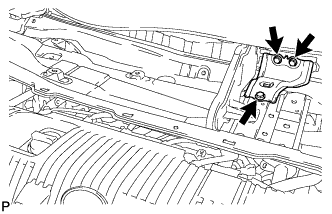
Remove the 3 bolts and cowl body mounting reinforcement LH.
| 5. REMOVE COWL BODY MOUNTING REINFORCEMENT LH (for RHD) |
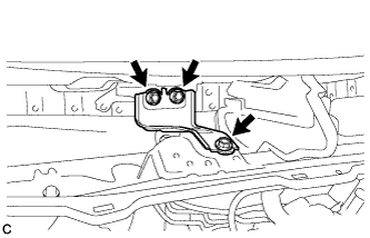 |
Remove the 3 bolts and cowl body mounting reinforcement LH.
| 6. REMOVE OUTER COWL TOP PANEL SUB-ASSEMBLY (for LHD) |
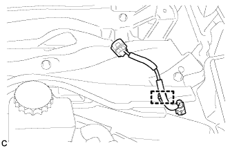 |
Disengage the clamp and separate the wire harness.
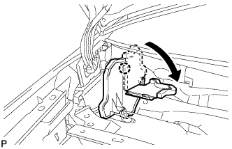 |
Disengage the claw and bend the No. 1 heater air duct splash shield seal.
 |
Disengage the claw and bend the water guard plate RH.
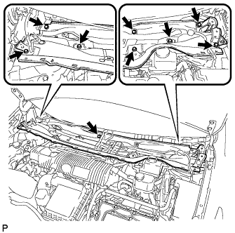 |
Remove the 9 bolts and outer cowl top panel sub-assembly.
| 7. REMOVE OUTER COWL TOP PANEL SUB-ASSEMBLY (for RHD) |
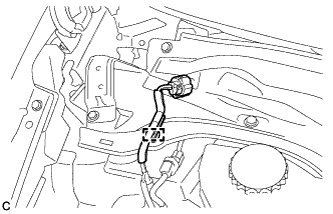 |
Disengage the clamp and separate the wire harness from the outer cowl top panel sub-assembly.
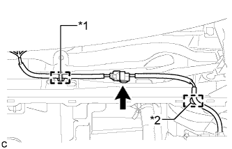 |
Disengage the clamp*1 and disconnect the connector (w/ Windshield Deicer).
Disengage the clamp*2 and separate the wire harness from the outer cowl top panel sub-assembly.
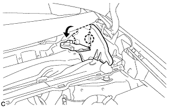 |
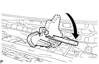
Disengage the claw and bend the No. 1 heater air duct splash shield seal.
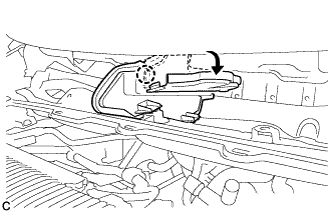 |
Disengage the claw and bend the water guard plate RH.
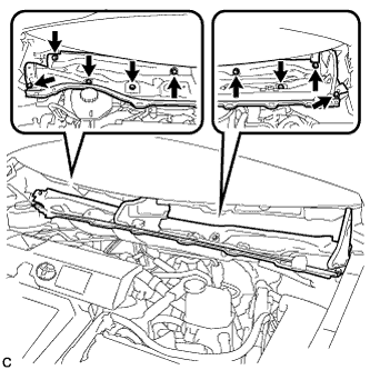 |
Remove the 9 bolts and outer cowl top panel sub-assembly.
| 8. DISCONNECT SUCTION PIPE SUB-ASSEMBLY |
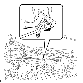 |
Remove the bolt and slide the hook connector.
Disconnect the suction pipe assembly.
Remove the O-ring from the suction pipe sub-assembly.
| 9. DISCONNECT AIR CONDITIONING TUBE AND ACCESSORY ASSEMBLY |
Disconnect the air conditioning tube and accessory assembly.
Remove the O-ring from the air conditioning tube and accessory assembly.
| 10. DISCONNECT INLET HEATER WATER HOSE |
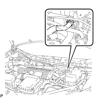 |
Using pliers, grip the claws of the clip and slide the clip to disconnect the inlet heater water hose.
| 11. DISCONNECT OUTLET HEATER WATER HOSE |
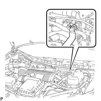 |
Using pliers, grip the claws of the clip and slide the clip to disconnect the outlet heater water hose.
| 12. REMOVE LOWER INSTRUMENT PANEL SUB-ASSEMBLY |
| 13. REMOVE HEADUP DISPLAY |
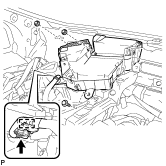 |
Disconnect the connector.
Disengage the clamp.
Remove the bolt, 2 nuts and headup display.
| 14. REMOVE ECU INTEGRATION BOX LH (for RHD) |
Disconnect each connector.
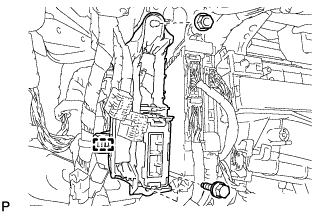 |
Disengage the clamp and disconnect the wire harness.
Remove the bolt, nut and ECU integration box.
| 15. REMOVE DRIVER SIDE JUNCTION BLOCK ASSEMBLY (for LHD) |
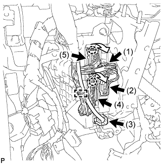 |
Disengage the clamp and disconnect the wire harness.
Disconnect the 3 connectors (1), (2) and (3).
Disengage the 2 claws and disconnect the 2 connectors (4) and (5) as shown in the illustration.
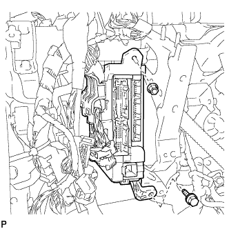 |
Remove the bolt and nut, and disconnect the driver side junction block assembly.
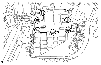 |
Disengage the 6 claws and remove the junction block bracket.
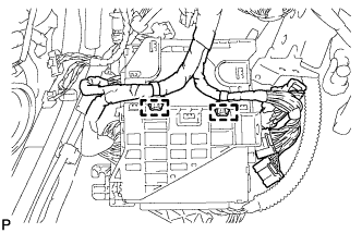 |
Disengage the 2 clamps and disconnect the wire harness.
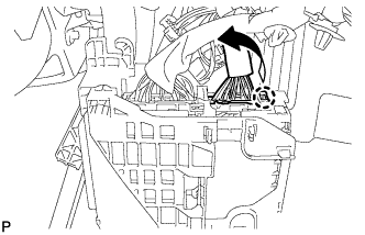 |
Disengage the claw and disconnect the connector as shown in the illustration.
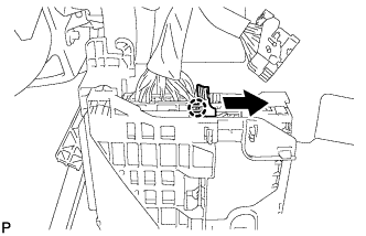 |
Disengage the claw and release the connector lock as shown in the illustration.
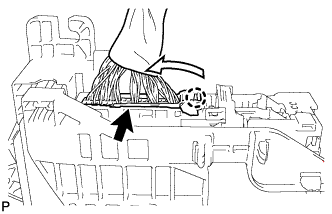 |
Disengage the claw and disconnect the connector as shown in the illustration.
Remove the driver side junction block assembly.
| 16. REMOVE FRONT PASSENGER SIDE JUNCTION BLOCK ASSEMBLY (for RHD) |
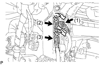 |
Disconnect the connector (1).
Disengage the 2 claws and disconnect the connector (2) and (3) as shown in the illustration.
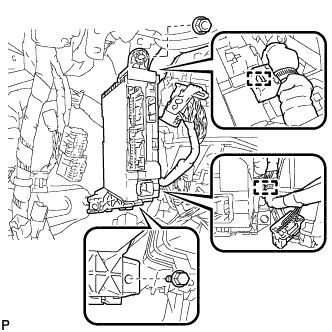 |
Disengage the 2 clamps and disconnect the wire harness.
Remove the bolt and nut, and disconnect the front passenger side junction block assembly.
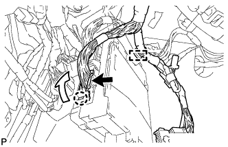 |
Disengage the clamp and disconnect the wire harness.
Disengage the claw and disconnect the connector as shown in the illustration.
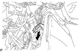 |
Disengage the claw and release the connector lock as shown in the illustration.
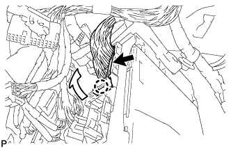 |
Disengage the claw and disconnect the connector as shown in the illustration.
Remove the front passenger side junction block assembly.
| 17. REMOVE STEERING POST ASSEMBLY |
| 18. REMOVE REAR NO. 2 AIR DUCT |
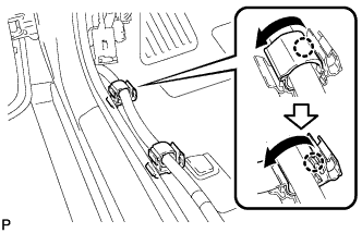 |
Disengage each claw to open the 2 door scuff plate clamps as shown in the illustration.
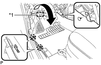 |
Disengage the clip and fastener.
Disengage the 2 claws and turn back the floor carpet as shown in the illustration.
| *1 | Fastener |
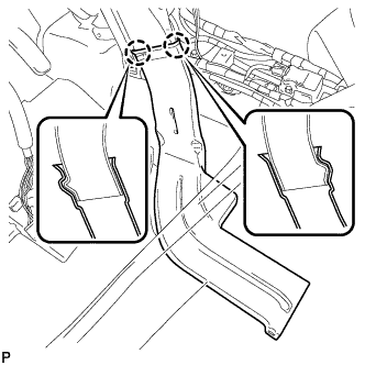 |
Disengage the 2 claws and remove the rear No. 2 air duct.
| 19. REMOVE REAR NO. 3 AIR DUCT |
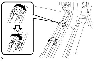 |
Disengage each claw to open the 2 door scuff plate clamps as shown in the illustration.
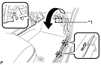 |
Disengage the clip and fastener.
Disengage the 2 claws and turn back the floor carpet as shown in the illustration.
| *1 | Fastener |
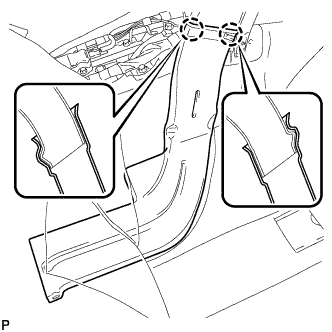 |
Disengage the 2 claws and remove the rear No. 3 air duct.
| 20. REMOVE REAR NO. 1 AIR DUCT |
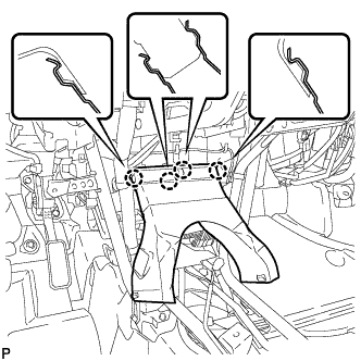 |
Disengage the 4 claws and remove the rear No. 1 air duct.
| 21. REMOVE NO. 3 SIDE DEFROSTER NOZZLE DUCT |
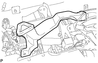 |
Remove the clip and No. 3 side defroster nozzle duct.
| 22. REMOVE NO. 1 INSTRUMENT PANEL BRACE SUB-ASSEMBLY |
Check that the power switch is off.
Check that the cable is disconnected from the negative (-) battery terminal.
Disconnect the center airbag sensor connectors from the center airbag sensor assembly as shown in the illustration.
Remove the screw.
Remove the 2 bolts and disconnect the 2 earth wires.
Disconnect each connector.
Disengage each clamp and claw.
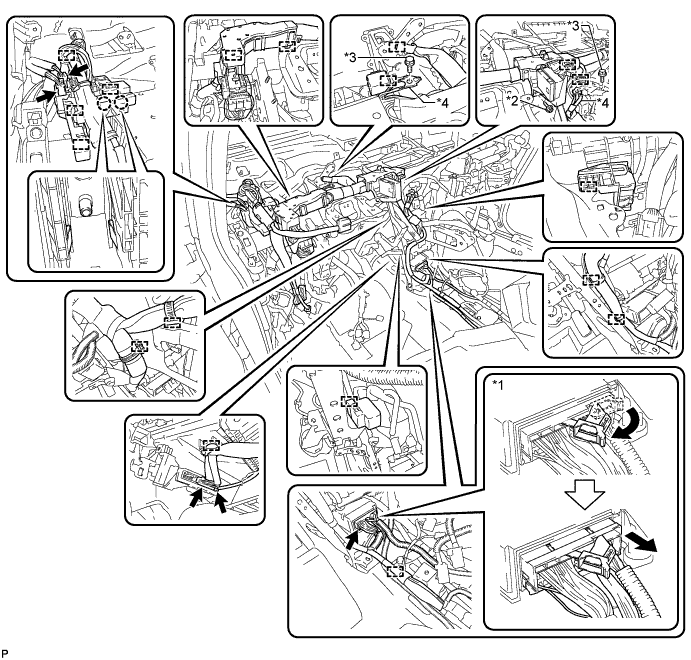
| *1 | Center airbag sensor connector | *2 | Screw |
| *3 | Bolt | *4 | Earth wires |
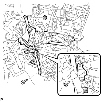 |
Remove the screw.
Remove the bolt, nut and No. 1 instrument panel brace sub-assembly.
| 23. REMOVE NO. 2 INSTRUMENT PANEL BRACE SUB-ASSEMBLY |
Remove the 3 screws <A>.
Remove the bolt and disconnect the earth wire.
Disconnect each connector.
Disengage each clamp.
Remove the screw <B> and 2 nuts from the computer integration box RH.
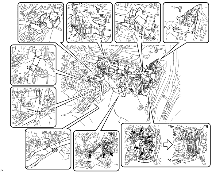
| *1 | Screw <A> | *2 | Bolt |
| *3 | Earth wires | *4 | Screw <B> |
| *5 | Nut | *6 | Computer integration box RH |
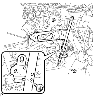 |
Remove the screw.
Remove the bolt, nut and No. 2 instrument panel brace sub-assembly.
| 24. REMOVE DEFROSTER NOZZLE ASSEMBLY |
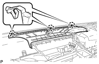 |
Disengage the 3 claws.
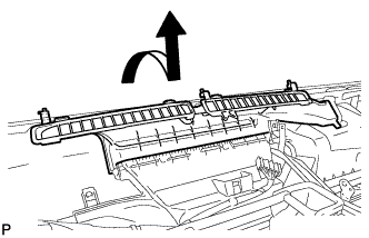 |
Remove the defroster nozzle assembly as shown in the illustration.
| 25. REMOVE LOWER DEFROSTER NOZZLE ASSEMBLY |
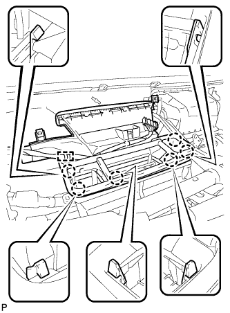 |
Disengage the clamp.
Disengage the 6 claws and remove the lower defroster nozzle assembly.
| 26. REMOVE NO. 3 AIR DUCT SUB-ASSEMBLY |
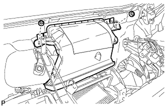 |
Remove the 2 nuts and No. 3 air duct sub-assembly.
| 27. REMOVE INSTRUMENT PANEL REINFORCEMENT ASSEMBLY |
Disengage each clamp.
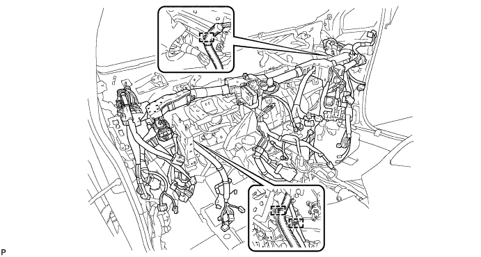
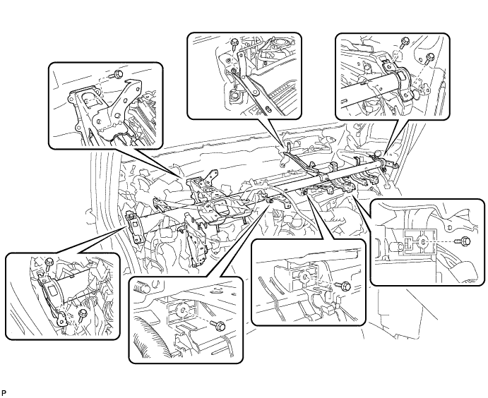
Remove the 9 bolts and instrument panel reinforcement assembly.
| 28. REMOVE AIR CONDITIONING UNIT ASSEMBLY |
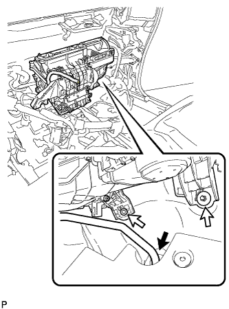 |
Disconnect the drain cooler hose.
Remove the bolt, nut and air conditioning unit assembly.