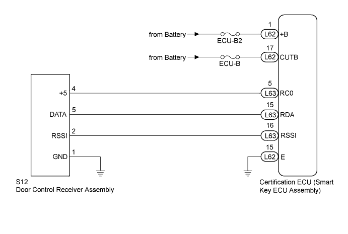
ENTRY AND START SYSTEM (for Entry Function) > All Door Entry Lock/Unlock Functions and Wireless Functions do not Operate |
| 1.CHECK POWER DOOR LOCK OPERATION |
When the door control switch on the master switch assembly is operated, check that the doors unlock and lock according to switch operation (Click here).
|
| ||||
| OK | |
 |
| 2.CHECK ELECTRICAL KEY TRANSMITTER |
Check if another registered key is available.
| Result | Proceed to |
| Another registered key is not available. | A |
| Another registered key is available. | B |
|
| ||||
| A | |
|
| 3.REGISTER ELECTRICAL KEY TRANSMITTER |
Register a new key.
| NEXT | |
|
| 4.CHECK ELECTRICAL KEY TRANSMITTER (OPERATION) |
Using the key registered in the previous step or another registered key, check that the entry function operates normally (Click here).
|
| ||||
| OK | |
|
| 5.CHECK ELECTRICAL KEY TRANSMITTER (LED) |
Check that the transmitter LED illuminates each time when the switch is pushed 3 times.
| Result | Proceed to |
| Transmitter LED does not illuminate at all when switch is pushed 3 times. | A |
| Transmitter LED illuminates each time when switch is pushed 3 times. | B |
| Transmitter LED does not illuminate the second or third time. | C |
|
| ||||
|
| ||||
| A | |
|
| 6.INSPECT TRANSMITTER BATTERY (VOLTAGE) |
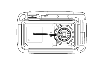 |
Remove the battery from the key that does not operate. Attach a lead wire (0.6 mm (0.0236 in.) or less in diameter including wire sheath) with tape or equivalent to the negative (-) terminal (Click here).
Carefully pull the lead wire out from the position shown in the illustration and install the previously removed transmitter battery.
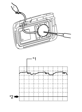 |
Using an oscilloscope, check the transmitter battery voltage waveform.
| Item | Content |
| Tester Connection | Battery positive (+) - Battery negative (-) |
| Tool Setting | 0.5 V/DIV., 100 ms/DIV. |
| Condition | Power switch off, all doors closed and lock switch pushed |
| Specified Condition | 2.2 to 3.2 V (Refer to the waveform) |
| *1 | Measurement Position |
| *2 | GND |
|
| ||||
| OK | ||
 | ||
| ||
| 7.CHECK WAVE ENVIRONMENT |
Bring the key near the door control receiver, and check the wireless function.
|
| ||||
| OK | ||
| ||
| ||
| 8.CHECK POWER SOURCE |
Check if functions other than the entry function operate when the power switch is off.
| Result | Proceed to |
| Other functions do not operate. | A |
| Other functions operate. | B |
|
| ||||
| A | |
|
| 9.INSPECT FUSES (ECU-B2, ECU-B) |
Remove the ECU-B2 and ECU-B fuses from the engine room relay block and junction block.
Measure the resistance according to the value(s) in the table below.
| Tester Connection | Condition | Specified Condition |
| ECU-B2 fuse | Always | Below 1 Ω |
| ECU-B fuse | Always | Below 1 Ω |
|
| ||||
| OK | |
|
| 10.CHECK HARNESS AND CONNECTOR (CERTIFICATION ECU - BATTERY AND BODY GROUND) |
Install the ECU-B2 and ECU-B fuses to the engine room relay block and junction block.
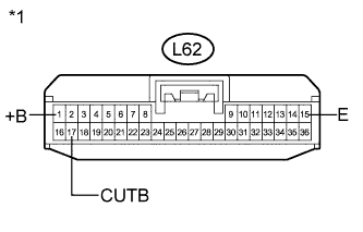 |
Disconnect the certification ECU (smart key ECU assembly) connector.
Measure the voltage and resistance according to the value(s) in the table below.
| Tester Connection | Condition | Specified Condition |
| L62-1 (+B) - Body ground | Except power switch on (READY) | 11 to 14 V |
| L62-1 (+B) - Body ground | Power switch on (READY) | 11 to 15.5 V |
| L62-17 (CUTB) - Body ground | Except power switch on (READY) | 11 to 14 V |
| L62-17 (CUTB) - Body ground | Power switch on (READY) | 11 to 15.5 V |
| Tester Connection | Condition | Specified Condition |
| L62-15 (E) - Body ground | Always | Below 1 Ω |
| *1 | Front view of wire harness connector (to Certification ECU (Smart Key ECU Assembly)) |
|
| ||||
| OK | |
|
| 11.CHECK HARNESS AND CONNECTOR (CERTIFICATION ECU - DOOR CONTROL RECEIVER) |
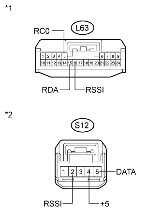 |
Disconnect the door control receiver assembly connector.
Measure the resistance according to the value(s) in the table below.
| Tester Connection | Condition | Specified Condition |
| L63-5 (RC0) - S12-4 (+5) | Always | Below 1 Ω |
| L63-15 (RDA) - S12-5 (DATA) | Always | Below 1 Ω |
| L63-16 (RSSI) - S12-2 (RSSI) | Always | Below 1 Ω |
| L63-5 (RC0) - Body ground | Always | 10 kΩ or higher |
| L63-15 (RDA) - Body ground | Always | 10 kΩ or higher |
| L63-16 (RSSI) - Body ground | Always | 10 kΩ or higher |
| S12-4 (+5) - Body ground | Always | 10 kΩ or higher |
| S12-5 (DATA) - Body ground | Always | 10 kΩ or higher |
| S12-2 (RSSI) - Body ground | Always | 10 kΩ or higher |
| *1 | Front view of wire harness connector (to Certification ECU (Smart Key ECU Assembly)) |
| *2 | Front view of wire harness connector (to Door Control Receiver Assembly) |
|
| ||||
| OK | |
|
| 12.CHECK HARNESS AND CONNECTOR (DOOR CONTROL RECEIVER - BODY GROUND) |
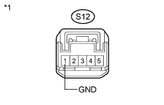 |
Measure the resistance according to the value(s) in the table below.
| Tester Connection | Condition | Specified Condition |
| S12-1 (GND) - Body ground | Always | Below 1 Ω |
| *1 | Front view of wire harness connector (to Door Control Receiver Assembly) |
|
| ||||
| OK | |
|
| 13.INSPECT DOOR CONTROL RECEIVER ASSEMBLY (POWER SOURCE) |
Reconnect the certification ECU (smart key ECU assembly) connector.
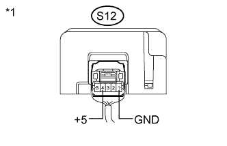 |
Reconnect the door control receiver assembly connector.
Measure the voltage according to the value(s) in the table below.
| Tester Connection | Condition | Specified Condition |
| S12-4 (+5) - S12-1 (GND) |
| Below 1 V |
| S12-4 (+5) - S12-1 (GND) |
| 4.5 to 5.5 V |
| *1 | Component with harness connected (Door Control Receiver Assembly) |
|
| ||||
| OK | |
|
| 14.INSPECT DOOR CONTROL RECEIVER ASSEMBLY (DOOR CONTROL RECEIVER SIGNAL OUTPUT) |
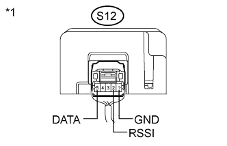 |
Measure the voltage according to the value(s) in the table below.
| Tester Connection | Condition | Specified Condition |
| S12-2 (RSSI) - S12-1 (GND) |
| 11 to 14 V |
| S12-2 (RSSI) - S12-1 (GND) |
| Below 2 V |
| S12-5 (DATA) - S12-1 (GND) | Power switch off | Pulse between 11 to 14 V occurs regularly |
| *1 | Component with harness connected (Door Control Receiver Assembly) |
|
| ||||
| OK | ||
| ||
| ||

