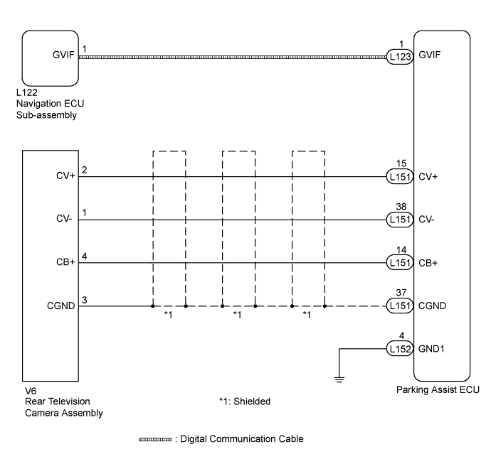
INTELLIGENT PARKING ASSIST SYSTEM > Image from Camera for Intelligent Parking Assist is Abnormal |
| 1.CHECK HARNESS AND CONNECTOR (PARKING ASSIST ECU - REAR TELEVISION CAMERA ASSEMBLY) |
Disconnect the L151 connector from the parking assist ECU.
Disconnect the V6 connector from the rear television camera assembly.
Measure the resistance according to the value(s) in the table below.
| Tester Connection | Condition | Specified Condition |
| L151-14 (CB+) - V6-4 (CB+) | Always | Below 1 Ω |
| L151-15 (CV+) - V6-2 (CV+) | Always | Below 1 Ω |
| L151-37 (CGND) - V6-3 (CGND) | Always | Below 1 Ω |
| L151-38 (CV-) - V6-1 (CV-) | Always | Below 1 Ω |
| L151-14 (CB+) - Body ground | Always | 10 kΩ or higher |
| L151-15 (CV+) - Body ground | Always | 10 kΩ or higher |
| L151-37 (CGND) - Body ground | Always | 10 kΩ or higher |
| L151-38 (CV-) - Body ground | Always | 10 kΩ or higher |
|
| ||||
| OK | |
 |
| 2.CHECK PARKING ASSIST ECU (CV-, CGND) |
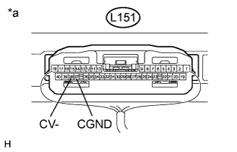 |
Reconnect the L151 connector to the parking assist ECU.
Measure the resistance according to the value(s) in the table below.
| Tester Connection | Condition | Specified Condition |
| L151-37 (CGND) - Body ground | Always | Below 1 Ω |
| L151-38 (CV-) - Body ground | Always | Below 1 Ω |
| *a | Component with harness connected (Parking Assist ECU) |
|
| ||||
| OK | |
|
| 3.CHECK HARNESS AND CONNECTOR (REAR TELEVISION CAMERA ASSEMBLY - POWER SOURCE) |
Disconnect the V6 connector from the rear television camera assembly.
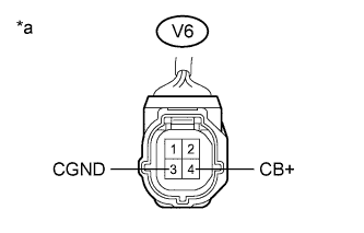 |
Measure the voltage according to the value(s) in the table below.
| Tester Connection | Condition | Specified Condition |
| V6-3 (CGND) - V6-4 (CB+) | Power switch on (READY) Reverse (R) selected | 5.8 to 7.0 V |
| *a | Front view of wire harness connector (to Rear Television Camera Assembly) |
|
| ||||
| OK | |
|
| 4.CHECK PARKING ASSIST ECU (CV+, GND1) |
Reconnect the V6 connector to the rear television camera assembly.
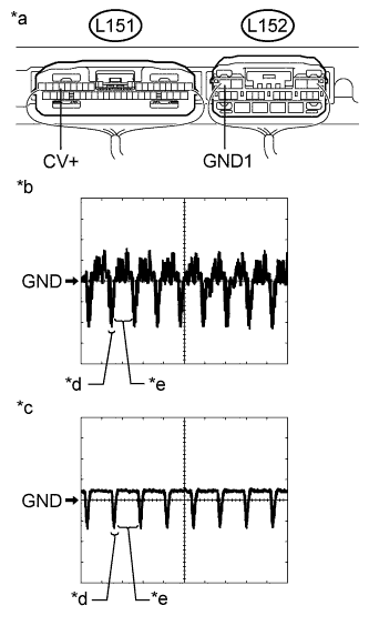 |
Reconnect the L151 connectors to the parking assist ECU.
Check the waveform of the rear television camera assembly using an oscilloscope.
| Item | Content |
| Terminal No. (Symbol) | L151-15 (CV+) - L152-4 (GND1) |
| Tool Setting | 200 mV/DIV., 50 μsec./DIV. |
| Condition | Power switch on (READY), reverse (R) selected |
| *a | Component with harness connected (Parking Assist ECU) |
| *b | Waveform 1 (camera lens not covered, displaying an image) |
| *c | Waveform 2 (camera lens covered, blacking out the screen) |
| *d | Synchronization Signal |
| *e | Video Waveform |
|
| ||||
| OK | |
|
| 5.READ VALUE USING INTELLIGENT TESTER |
Connect the intelligent tester to the DLC3.
Turn the power switch on (IG).
Turn the intelligent tester on.
Enter the following menus: Chassis / Intelligent Parking Assist / Data List.
Check the Data List for proper functioning of the following items.
| Tester Display | Measurement Item/Range | Normal Condition | Diagnostic Note |
| ASIC Output Status | Output condition of camera display/OK or NG | OK: Output condition of camera display is normal NG: Output condition of camera display is abnormal | - |
|
| ||||
| OK | |
|
| 6.CHECK DIGITAL COMMUNICATION CABLE CONNECTOR |
Check the digital communication cable connectors.
Check the digital communication cable connectors between the parking assist ECU and navigation ECU sub-assembly for any connection problems (Click here).
Check if the same malfunction recurs when the intelligent parking assist screen is displayed.
| Result | Proceed to |
| Malfunction does not reoccur (returns to normal) | A |
| Malfunction reoccurs | B |
|
| ||||
| A | ||
 | ||
| ||
| 7.REPLACE WIRE HARNESS (DIGITAL COMMUNICATION CABLE) |
Replace the digital communication cable between the parking assist ECU and navigation receiver assembly with a new one.
Check if the same malfunction recurs when the intelligent parking assist screen is displayed.
| Result | Proceed to |
| Malfunction does not reoccur (returns to normal) | A |
| Malfunction reoccurs | B |
|
| ||||
| A | ||
| ||
| ||
| 8.REPLACE NAVIGATION ECU SUB-ASSEMBLY |
Replace the navigation ECU sub-assembly with a new or known good one (Click here).
Check if the same malfunction recurs when the intelligent parking assist screen is displayed.
| Result | Proceed to |
| Malfunction does not reoccur | A |
| Malfunction reoccurs | B |
|
| ||||
| A | ||
| ||
| ||

