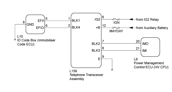
BLOCKING SYSTEM > Power Source Mode does not Change to ON (READY) |
| 1.CHECK DTC OUTPUT |
Clear the DTCs (Click here).
Turn the power switch off.
Turn the power switch on (IG).
After 10 seconds have elapsed, check for DTCs.
| Result | Proceed to |
| DTC is not output. | A |
| Hybrid control system DTC is output. | B |
| Engine immobiliser system DTC is output. | C |
| Entry and start system (for start function) DTC is output. | D |
| Blocking system DTC is output. | E |
|
| ||||
|
| ||||
|
| ||||
|
| ||||
| A | |
 |
| 2.CHECK WHETHER HYBRID CONTROL SYSTEM STARTS |
Check that the hybrid control system starts normally.
|
| ||||
| OK | ||
 | ||
| ||
| 3.CHECK BLOCKING SYSTEM (SETTING) |
Check the blocking system setting.
| Result | Proceed to |
| Blocking system is unset. | A |
| Blocking system is set. | B |
|
| ||||
| A | |
|
| 4.CHECK SECURITY INDICATOR LIGHT (ENGINE IMMOBILISER SYSTEM UNSET) |
Get into the vehicle while carrying an electrical key transmitter sub-assembly.
Check that park (P) has been selected.
Press the power switch with the brake pedal released and check that the security indicator light changes from blinking to off at the same time the power source mode changes to on (ACC).
|
| ||||
| OK | |
|
| 5.CHECK WHETHER HYBRID CONTROL SYSTEM STARTS |
Turn the power switch on (IG).
After 5 seconds have elapsed, start the hybrid control system.
|
| ||||
| OK | ||
| ||
| ||
| 6.CHECK TELEPHONE TRANSCEIVER ASSEMBLY |
Using an oscilloscope, check the waveform.
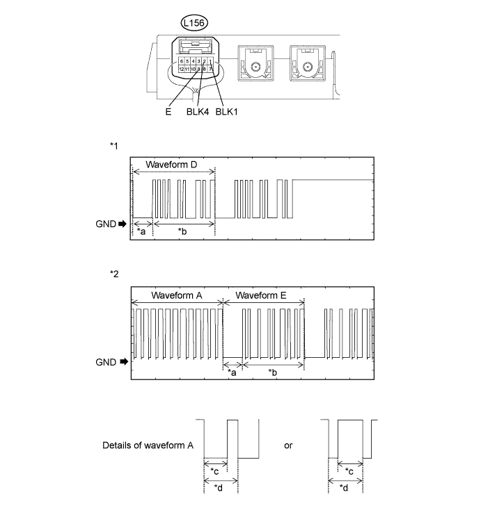
| *1 | Waveform 1 | *2 | Waveform 2 |
| *a | Approximately 160 ms | *b | Approximately 510 ms |
| *c | Approximately 40 ms | *d | Approximately 60 ms |
| Tester Connection | Condition | Tool Setting | Specified Condition |
| L156-1 (BLK1) - L156-9 (E) | Check the waveform when the hybrid control system is started or the moment the power switch is turned on (IG) after the cable was disconnected and reconnected to the negative (-) auxiliary battery terminal. | 2 V/DIV., 500 ms./DIV. | Pulse generation (See waveform 1) |
| L156-2 (BLK4) - L156-9 (E) | Check the waveform when the hybrid control system is started or the moment the power switch is turned on (IG) after the cable was disconnected and reconnected to the negative (-) auxiliary battery terminal. | 2 V/DIV., 500 ms./DIV. | Pulse generation (See waveform 2) |
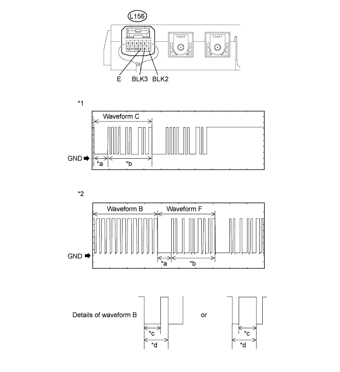
| *1 | Waveform 1 | *2 | Waveform 2 |
| *a | Approximately 160 ms | *b | Approximately 510 ms |
| *c | Approximately 40 ms | *d | Approximately 60 ms |
| Tester Connection | Condition | Tool Setting | Specified Condition |
| L156-7 (BLK2) - L156-9 (E) | Check the waveform when the hybrid control system is started or the moment the power switch is turned on (IG) after the cable was disconnected and reconnected to the negative (-) auxiliary battery terminal. | 2 V/DIV., 500 ms./DIV. | Pulse generation (See waveform 1) |
| L156-8 (BLK3) - L156-9 (E) | Check the waveform when the hybrid control system is started or the moment the power switch is turned on (IG) after the cable was disconnected and reconnected to the negative (-) auxiliary battery terminal. | 2 V/DIV., 500 ms./DIV. | Pulse generation (See waveform 2) |
| Result | Proceed to |
| OK | A |
| Waveform A is abnormal Waveform E is abnormal | B |
| Waveform B is abnormal Waveform F is abnormal | C |
| Waveform C is abnormal | D |
| Waveform D is abnormal | E |
|
| ||||
|
| ||||
|
| ||||
|
| ||||
| A | |
|
| 7.REREGISTRATION |
Reregister the communication ID.
| NEXT | |
|
| 8.CHECK WHETHER HYBRID CONTROL SYSTEM STARTS |
Check if the problem symptom occurs when the hybrid control system is started using a registered key.
|
| ||||
| OK | ||
| ||
| ||
| 9.CHECK HARNESS AND CONNECTOR (TELEPHONE TRANSCEIVER ASSEMBLY - ID CODE BOX (IMMOBILISER CODE ECU)) |
Disconnect the L156 telephone transceiver assembly connector.
Disconnect the L10 ID code box (immobiliser code ECU) connector.
Measure the resistance according to the value(s) in the table below.
| Tester Connection | Condition | Specified Condition |
| L156-2 (BLK4) - L10-6 (EFIO) | Always | Below 1 Ω |
| L156-2 (BLK4) - Body ground | Always | 10 kΩ or higher |
| L10-6 (EFIO) - Body ground | Always | 10 kΩ or higher |
|
| ||||
| OK | |
|
| 10.REPLACE ID CODE BOX (IMMOBILISER CODE ECU) |
Temporarily replace the ID code box (immobiliser code ECU) with a new one.
| NEXT | |
|
| 11.PERFORM REGISTRATION |
Perform the registration.
| NEXT | |
|
| 12.CHECK WHETHER HYBRID CONTROL SYSTEM STARTS |
Check that the hybrid control system starts normally.
|
| ||||
| OK | ||
| ||
| ||
| 13.CHECK HARNESS AND CONNECTOR (TELEPHONE TRANSCEIVER ASSEMBLY - POWER MANAGEMENT CONTROL ECU) |
Disconnect the L156 telephone transceiver assembly connector.
Disconnect the L6 power management control ECU connector.
Measure the resistance according to the value(s) in the table below.
| Tester Connection | Condition | Specified Condition |
| L156-8 (BLK3) - L6-21 (IMI) | Always | Below 1 Ω |
| L156-8 (BLK3) - Body ground | Always | 10 kΩ or higher |
| L6-21 (IMI) - Body ground | Always | 10 kΩ or higher |
|
| ||||
| OK | |
|
| 14.REPLACE TELEPHONE TRANSCEIVER ASSEMBLY |
Temporarily replace the telephone transceiver assembly with a new one.
| NEXT | |
|
| 15.PERFORM REGISTRATION |
Perform the registration.
| NEXT | |
|
| 16.CHECK WHETHER HYBRID CONTROL SYSTEM STARTS |
Check that the hybrid control system starts normally.
|
| ||||
| OK | ||
| ||
| ||
| 17.REPLACE POWER MANAGEMENT CONTROL ECU |
Temporarily replace the power management control ECU with a new one (Click here).
| NEXT | |
|
| 18.CHECK DTC OUTPUT |
Clear the DTCs (Click here).
Turn the power switch off.
Turn the power switch on (IG).
After 10 seconds have elapsed, check for DTCs.
| Result | Proceed to |
| DTC is not output. | A |
| Hybrid control system DTC is output. | B |
| Engine immobiliser system DTC is output. | C |
| Entry and start system (for start function) DTC is output. | D |
| Blocking system DTC is output. | E |
|
| ||||
|
| ||||
|
| ||||
|
| ||||
| A | ||
| ||
| ||
| 19.CHECK HARNESS AND CONNECTOR (TELEPHONE TRANSCEIVER ASSEMBLY - POWER MANAGEMENT CONTROL ECU) |
Disconnect the L156 telephone transceiver assembly connector.
Disconnect the L6 power management control ECU connector.
Measure the resistance according to the value(s) in the table below.
| Tester Connection | Condition | Specified Condition |
| L156-7 (BLK2) - L6-20 (IMO) | Always | Below 1 Ω |
| L156-7 (BLK2) - Body ground | Always | 10 kΩ or higher |
| L6-20 (IMO) - Body ground | Always | 10 kΩ or higher |
|
| ||||
| OK | |
|
| 20.REPLACE POWER MANAGEMENT CONTROL ECU |
Temporarily replace the power management control ECU with a new one (Click here).
| NEXT | |
|
| 21.CHECK DTC OUTPUT |
Clear the DTCs (Click here).
Turn the power switch off.
Turn the power switch on (IG).
After 10 seconds have elapsed, check for DTCs.
| Result | Proceed to |
| DTC is not output. | A |
| Hybrid control system DTC is output. | B |
| Engine immobiliser system DTC is output. | C |
| Entry and start system (for start function) DTC is output. | D |
| Blocking system DTC is output. | E |
|
| ||||
|
| ||||
|
| ||||
|
| ||||
| A | |
|
| 22.CHECK WHETHER HYBRID CONTROL SYSTEM STARTS |
Check that the hybrid control system starts normally.
|
| ||||
| OK | ||
| ||
| ||
| 23.CHECK HARNESS AND CONNECTOR (TELEPHONE TRANSCEIVER ASSEMBLY - ID CODE BOX (IMMOBILISER CODE ECU)) |
Disconnect the L156 telephone transceiver assembly connector.
Disconnect the L10 ID code box (immobiliser code ECU) connector.
Measure the resistance according to the value(s) in the table below.
| Tester Connection | Condition | Specified Condition |
| L156-1 (BLK1) - L10-5 (EFII) | Always | Below 1 Ω |
| L156-1 (BLK1) - Body ground | Always | 10 kΩ or higher |
| L10-5 (EFII) - Body ground | Always | 10 kΩ or higher |
|
| ||||
| OK | |
|
| 24.REPLACE TELEPHONE TRANSCEIVER ASSEMBLY |
Temporarily replace the telephone transceiver assembly with a new one.
| NEXT | |
|
| 25.PERFORM REGISTRATION |
Perform the registration.
| NEXT | |
|
| 26.CHECK WHETHER HYBRID CONTROL SYSTEM STARTS |
Check that the hybrid control system starts normally.
|
| ||||
| OK | ||
| ||
| ||

