 |
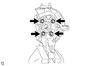
Install the front axle hub sub-assembly and front disc brake dust cover with the 4 bolts.
- Torque:
- 40 N*m{ 408 kgf*cm , 30 ft.*lbf }
FRONT AXLE HUB > INSTALLATION |
| 1. INSTALL FRONT AXLE HUB SUB-ASSEMBLY |
Secure the steering knuckle between aluminum plates in a vise.
|
Install the front axle hub sub-assembly and front disc brake dust cover with the 4 bolts.
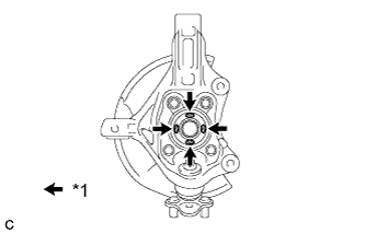 |
Apply MP grease to the areas indicated by the arrows in the illustration on the front drive shaft assembly contact surface of the front axle hub sub-assembly.
| *1 | MP grease |
| 2. INSTALL FRONT AXLE ASSEMBLY |
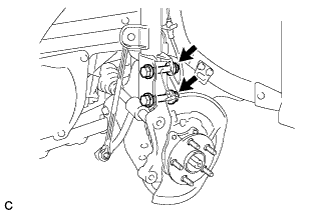 |
Install the front axle assembly to the front shock absorber with the 2 bolts and 2 nuts.
| 3. INSTALL FRONT DRIVE SHAFT ASSEMBLY |
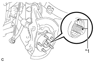 |
Align the matchmarks and install the front drive shaft assembly to the front axle hub sub-assembly.
| *1 | Matchmark |
| 4. INSTALL FRONT NO. 1 LOWER SUSPENSION ARM SUB-ASSEMBLY |
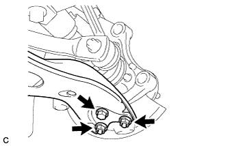 |
Install the front No. 1 lower suspension arm sub-assembly to the front lower ball joint with the bolt and 2 nuts.
| 5. CONNECT TIE ROD END SUB-ASSEMBLY |
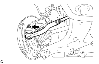 |
Connect the tie rod end sub-assembly LH to the steering knuckle with the nut.
Install a new clip.
| 6. INSTALL FRONT DISC |
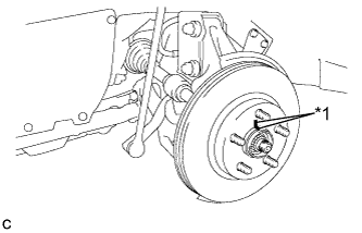 |
Align the matchmarks of the disc and axle hub, and install the disc.
| *1 | Matchmark |
| 7. INSTALL FRONT DISC BRAKE CALIPER ASSEMBLY |
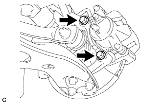 |
Install the front disc brake caliper assembly to the steering knuckle with the 2 bolts.
| 8. TEMPORARILY INSTALL FRONT AXLE SHAFT NUT |
Clean the threaded parts on the front drive shaft assembly and a new front axle shaft nut using a non-residue solvent.
Using a socket wrench (30 mm), while applying the brakes, temporarily install the front axle shaft nut.
| 9. SEPARATE FRONT DISC BRAKE CALIPER ASSEMBLY |
|
Remove the 2 bolts and separate the front disc brake caliper assembly.
| 10. REMOVE FRONT DISC |
|
Remove the front disc.
| *1 | Matchmark |
| 11. INSPECT FRONT AXLE HUB BEARING LOOSENESS |
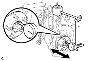 |
Using a dial indicator, check for looseness near the center of the axle hub.
| 12. INSPECT FRONT AXLE HUB RUNOUT |
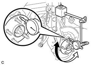 |
Using a dial indicator, check for runout on the surface of the axle hub outside the hub bolt.
| 13. INSTALL FRONT DISC |
|
Align the matchmarks of the disc and axle hub, and install the disc.
| *1 | Matchmark |
| 14. INSTALL FRONT DISC BRAKE CALIPER ASSEMBLY |
|
Install the front disc brake caliper assembly to the steering knuckle with the 2 bolts.
| 15. INSTALL FRONT FLEXIBLE HOSE |
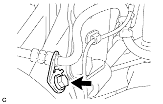 |
Install the front flexible hose to the steering knuckle with the bolt.
| 16. INSTALL FRONT SPEED SENSOR |
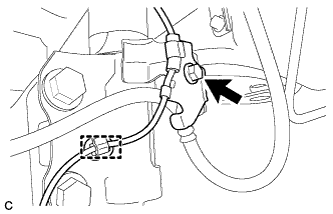 |
Install the front speed sensor and front flexible hose to the front shock absorber with the bolt and clamp.
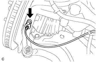 |
Install the front speed sensor to the steering knuckle with the bolt.
| 17. INSTALL FRONT AXLE SHAFT NUT |
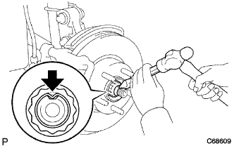 |
Using a chisel and hammer, stake the front axle shaft nut.
| 18. INSTALL FRONT WHEEL |
| 19. CONNECT CABLE TO AUXILIARY BATTERY NEGATIVE TERMINAL |
Connect the cable to the negative (-) auxiliary battery terminal.
Connect the reservoir level switch connector.
Clear the DTCs (Click here).
| 20. INSTALL REAR NO. 3 FLOOR BOARD |
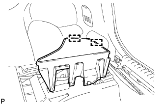 |
Engage the 2 guides to install the rear No. 3 floor board.
| 21. INSTALL REAR DECK FLOOR BOX |
Install the rear deck floor box.
| 22. INSTALL REAR NO. 2 FLOOR BOARD (for Separate Type) |
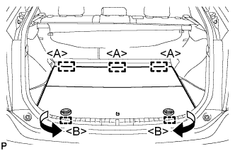 |
Engage the 3 guides <A>.
Engage the 2 guides <B> and install the rear No. 2 floor board as shown in the illustration.
| 23. INSPECT AND ADJUST FRONT WHEEL ALIGNMENT |
| 24. CHECK FOR SPEED SENSOR SIGNAL |