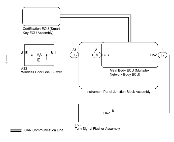
WIRELESS DOOR LOCK CONTROL SYSTEM > No Answer-Back |
| 1.READ VALUE USING TECHSTREAM (ANSWER-BACK OPERATION) |
Connect the Techstream to the DLC3.
Turn the power switch on (IG).
Turn the Techstream on.
Enter the following menus: Body Electrical / Main Body / Utility / Customize.
Select the setting by referring to the table below.
| Display (item) | Default | Function | Setting |
| Hazard Answer Back | ON | When the doors are locked by wireless operation, the hazard warning lights flash once. When the doors are unlocked by wireless operation, the hazard warning lights flash twice. | ON or OFF |
| Wireless Buzzer Resp | ON | Wireless door lock buzzer response on or off | ON or OFF |
| Result | Proceed to |
| Both items are on. | A |
| Either item is off. | B |
|
| ||||
| A | |
 |
| 2.CHECK WIRELESS DOOR LOCK CONTROL FUNCTIONS |
Check the wireless door lock control function by the electrical key transmitter.
| Result | Proceed to |
| Wireless door lock/unlock operates normally. | A |
| Wireless door lock/unlock does not operate normally. | B |
|
| ||||
| A | |
|
| 3.READ VALUE USING TECHSTREAM (DOOR LOCK POSITION SWITCH) |
Connect the Techstream to the DLC3.
Turn the power switch on (IG).
Turn the Techstream on.
Enter the following menus: Body Electrical / Main Body / Data List.
Read the Data List according to the display on the Techstream.
| Tester Display | Measurement Item/Range | Normal Condition | Diagnostic Note |
| FR Door Lock Pos | Front passenger side door lock position switch signal/LOCK or UNLOCK | LOCK: Front passenger side door locked UNLOCK: Front passenger side door unlocked | - |
| FL Door Lock Pos | Driver door lock position switch signal/LOCK or UNLOCK | LOCK: Driver door locked UNLOCK: Driver door unlocked | - |
| RR-Door Lock Pos SW | Rear right side door lock position switch signal/ON or OFF | ON: Rear right side door unlocked OFF: Rear right side door locked | - |
| RL-Door Lock Pos SW | Rear left side door lock position switch signal/ON or OFF | ON: Rear left side door unlocked OFF: Rear left side door locked | - |
| Result | Proceed to |
| OK | A |
| NG (for Driver Side) | B |
| NG (for Front Passenger Side) | C |
| NG (for Rear LH Side) | D |
| NG (for Rear RH Side) | E |
|
| ||||
|
| ||||
|
| ||||
|
| ||||
| A | |
|
| 4.CHECK WIRELESS ANSWER-BACK OPERATION |
Check the wireless answer-back operation by wireless door lock control function.
| Result | Proceed to |
| Only hazard warning light answer-back does not occur. | A |
| Only wireless door lock buzzer answer-back does not occur. | B |
|
| ||||
| A | |
|
| 5.CHECK HAZARD WARNING LIGHT OPERATION |
Check that the hazard warning lights flash continuously when the hazard warning signal switch is pressed.
|
| ||||
| OK | |
|
| 6.PERFORM ACTIVE TEST USING TECHSTREAM |
Connect the Techstream to the DLC3.
Turn the power switch on (IG).
Turn the Techstream on.
Enter the following menus: Body Electrical / Main Body / Active Test.
Perform the Active Test according to the display on the Techstream.
| Tester Display | Test Part | Control Range | Diagnostic Note |
| Hazard | Turn signal flasher relay | ON/OFF | Observe headlights and rear combination lights for correct operation |
| Result | Proceed to |
| Turn signal flasher relay does not turn on/off. | A |
| Turn signal flasher relay turns on/off. | B |
|
| ||||
| A | |
|
| 7.CHECK HARNESS AND CONNECTOR (TURN SIGNAL FLASHER ASSEMBLY - MAIN BODY ECU) |
Disconnect the L55 turn signal flasher assembly and L7 main body ECU (multiplex network body ECU) connectors.
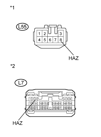 |
Measure the resistance according to the value(s) in the table below.
| Tester Connection | Condition | Specified Condition |
| L55-8 (HAZ) - L7-3 (HAZ) | Always | Below 1 Ω |
| L55-8 (HAZ) - Body ground | Always | 10 kΩ or higher |
| *1 | Front view of wire harness connector (to Turn Signal Flasher Assembly) |
| *2 | Front view of wire harness connector (to Main Body ECU (Multiplex Network Body ECU)) |
|
| ||||
| OK | ||
 | ||
| ||
| 8.PERFORM ACTIVE TEST USING TECHSTREAM (WIRELESS DOOR LOCK BUZZER) |
Connect the Techstream to the DLC3.
Turn the power switch on (IG).
Turn the Techstream on.
Enter the following menus: Body Electrical / Main Body / Active Test.
Perform the Active Test according to the display on the Techstream.
| Tester Display | Test Part | Control Range | Diagnostic Note |
| Wireless Buzzer | Turns the wireless door lock buzzer | ON/OFF | - |
| Result | Proceed to |
| Wireless door lock buzzer does not turn on/off. | A |
| Wireless door lock buzzer turns on/off. | B |
|
| ||||
| A | |
|
| 9.CHECK HARNESS AND CONNECTOR (WIRELESS DOOR LOCK BUZZER - INSTRUMENT PANEL JUNCTION BLOCK) |
Disconnect the A33 wireless door lock buzzer and 2C instrument panel junction block assembly connectors.
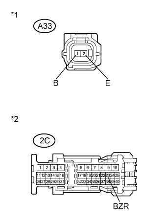 |
Measure the resistance according to the value(s) in the table below.
| Tester Connection | Condition | Specified Condition |
| A33-1 (B) - 2C-23 (BZR) | Always | Below 1 Ω |
| A33-2 (E) - Body ground | Always | Below 1 Ω |
| A33-1 (B) - Body ground | Always | 10 kΩ or higher |
| *1 | Front view of wire harness connector (to Wireless Door Lock Buzzer) |
| *2 | Front view of wire harness connector (to instrument panel junction block assembly) |
|
| ||||
| OK | |
|
| 10.CHECK INSTRUMENT PANEL JUNCTION BLOCK ASSEMBLY |
Remove the instrument panel junction block assembly (Click here).
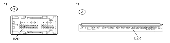
| *1 | Component without harness connected (instrument panel junction block assembly) |
Measure the resistance according to the value(s) in the table below.
| Tester Connection | Condition | Specified Condition |
| 2C-23 (BZR) - A-21 (BZR) | Always | Below 1 Ω |
|
| ||||
| OK | |
|
| 11.REPLACE WIRELESS DOOR LOCK BUZZER |
Temporarily replace the wireless door lock buzzer with a new one (Click here).
| NEXT | |
|
| 12.CHECK WIRELESS DOOR LOCK BUZZER OPERATION |
Check the operation of the wireless answer-back function.
|
| ||||
| OK | ||
| ||
| ||
| 13.REPLACE MAIN BODY ECU (MULTIPLEX NETWORK BODY ECU) |
Temporarily replace the main body ECU (multiplex network body ECU) with a new one (Click here).
| NEXT | |
|
| 14.CHECK WIRELESS DOOR LOCK BUZZER OPERATION |
Check the operation of the wireless function.
|
| ||||
| OK | ||
| ||
| ||

