 |
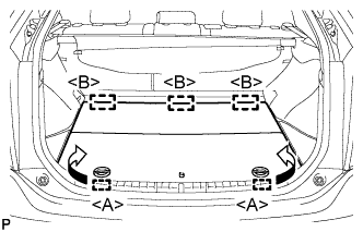
Disengage the 2 guides <A> as shown in the illustration.
COMPRESSOR > REMOVAL |
| 1. PRECAUTION |
| 2. RECOVER REFRIGERANT FROM REFRIGERATION SYSTEM |
Turn the A/C switch on.
Operate the A/C with the setting temperature at 25°C (77°F) and the blower level at LO for 10 minutes to circulate the refrigerant. This causes most of the compressor oil from the various components of the A/C system to collect in the A/C compressor.
Turn the power switch off.
Recover the refrigerant from the A/C system using a refrigerant recovery unit.
| 3. REMOVE REAR NO. 2 FLOOR BOARD (for Separate Type) |
|
Disengage the 2 guides <A> as shown in the illustration.
Disengage the 3 guides <B> and remove the rear No. 2 floor board.
| 4. REMOVE REAR DECK FLOOR BOX |
Remove the rear deck floor box.
| 5. REMOVE REAR NO. 3 FLOOR BOARD |
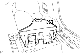 |
Disengage the 2 guides and remove the rear No. 3 floor board.
| 6. DISCONNECT CABLE FROM AUXILIARY BATTERY NEGATIVE TERMINAL |
| 7. REMOVE SERVICE PLUG GRIP |
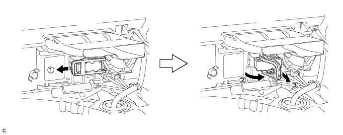
Wear insulating gloves and remove the service plug grip after sliding up the lever of the service plug grip as shown in the illustration.
| 8. CHECK TERMINAL VOLTAGE |
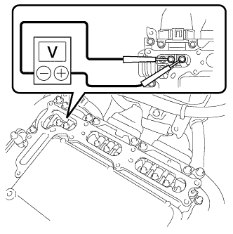 |
Using a voltmeter, measure the voltage between the terminals of the 2 phase connectors.
| 9. REMOVE INLET AIR CLEANER ASSEMBLY |
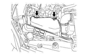 |
Remove the 2 bolts and inlet air cleaner assembly.
| 10. REMOVE NO. 1 ENGINE UNDER COVER |
| 11. DISCONNECT DISCHARGE HOSE SUB-ASSEMBLY |
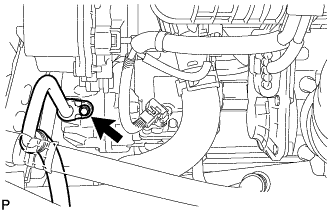 |
Remove the bolt and disconnect the discharge hose sub-assembly from the compressor with motor assembly.
Remove the O-ring from the discharge hose sub-assembly.
| 12. DISCONNECT SUCTION HOSE SUB-ASSEMBLY |
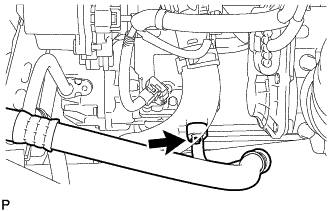 |
Remove the bolt and disconnect the suction hose sub-assembly from the compressor with motor assembly.
Remove the O-ring from the suction hose sub-assembly.
| 13. REMOVE COMPRESSOR WITH MOTOR ASSEMBLY |
for Type A:
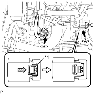 |
Using a screwdriver, slide the green-colored lock of the connector <A> in the direction indicated by the arrow in the illustration to release it and disconnect the connector.
| *1 | Green-colored Lock |
Disconnect the connector <B>.
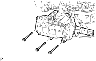 |
Remove the 3 bolts and compressor with motor assembly.
for Type B:
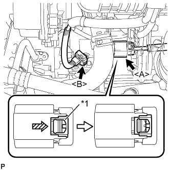 |
Using a screwdriver, slide the green-colored lock of the connector <A> in the direction indicated by the arrow in the illustration to release it and disconnect the connector.
| *1 | Green-colored Lock |
Disconnect the connector <B>.
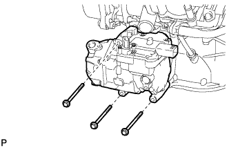 |
Remove the 3 bolts and compressor with motor assembly.