 |
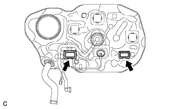
Install 2 new fuel tank cover vent case sub-assemblies as shown in the illustration.
FUEL TANK > INSTALLATION |
| 1. INSTALL FUEL TANK COVER VENT CASE SUB-ASSEMBLY |
|
Install 2 new fuel tank cover vent case sub-assemblies as shown in the illustration.
| 2. INSTALL NO. 1 FUEL TANK CUSHION |
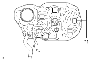 |
Install 3 new No. 1 fuel tank cushions as shown in the illustration.
| *1 | No. 1 Fuel Tank Cushion |
| 3. INSTALL FUEL TANK ASSEMBLY |
Support the fuel tank using an engine lifter.
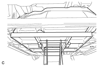 |
Raise the engine lifter, then install the fuel tank to the vehicle.
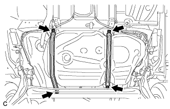 |
Tighten the 4 set bolts of the 2 fuel tank bands.
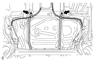 |
Connect the parking brake cable assembly with the 2 bolts.
| 4. CONNECT FUEL TANK MAIN TUBE SUB-ASSEMBLY |
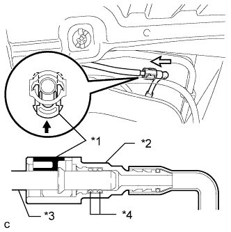 |
Push in the fuel tank main tube connector to the pipe and push up the retainer so that the claws engage.
| *1 | Retainer |
| *2 | Quick Connector |
| *3 | Pipe |
| *4 | O-ring |
| 5. CONNECT FUEL TANK TO FILLER PIPE HOSE |
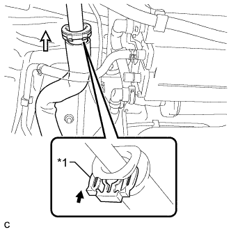 |
Push in the hose connector to the filler pipe and install the retainer.
| *1 | Retainer |
| 6. CONNECT FUEL TANK BREATHER TUBE |
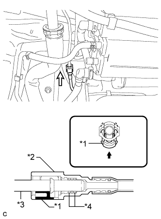 |
Push in the fuel tank breather tube connector to the pipe and push up the retainer so that the claws engage.
| *1 | Retainer |
| *2 | Quick Connector |
| *3 | Pipe |
| *4 | O-ring |
| 7. CONNECT FUEL CUT-OFF TUBE |
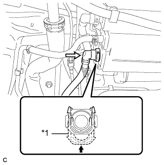 |
Push in the fuel cut-off tube connector to the charcoal canister and push up the retainer so that the claws engage.
| *1 | Retainer |
| 8. INSTALL NO. 1 FUEL TANK PROTECTOR |
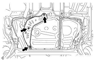 |
Install the No. 1 fuel tank protector with the 3 bolts.
| 9. INSTALL REAR FLOOR STEP UNDER COVER SUB-ASSEMBLY (w/ Floor Under Cover) |
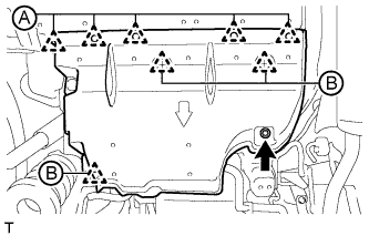 |
Connect the 3 clips (B).
Install the rear floor step under cover sub-assembly with the nut and 5 clips (A).
| 10. INSTALL REAR SUSPENSION BRACE SUB-ASSEMBLY |
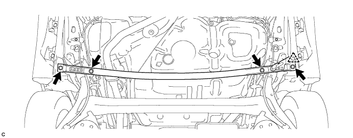
Install the rear suspension brace sub-assembly with the 4 bolts and clip.
| 11. INSTALL REAR FLOOR SIDE MEMBER COVER LH (w/ Floor Under Cover) |
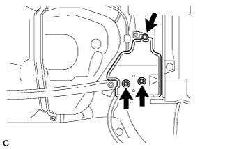 |
Install the rear floor side member cover LH with the nut and 2 bolts.
| 12. INSTALL REAR FLOOR SIDE MEMBER COVER RH (w/ Floor Under Cover) |
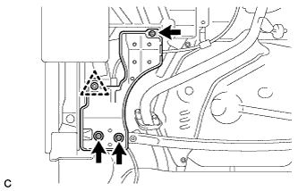 |
Engage the clip to temporarily install the rear floor side member cover RH.
Install the rear floor side member cover RH with the 3 bolts.
| 13. ADD FUEL |
| 14. INSTALL FUEL SUCTION TUBE ASSEMBLY WITH PUMP AND GAUGE |
Install the fuel suction tube assembly with pump and gauge (Click here).