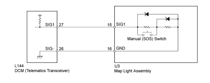
DTC B15C5 Manual Button Malfunction |
| DTC No. | DTC Detection Condition | Trouble Area |
| B15C5 | Open or short circuit in manual (SOS) switch is detected. |
|
| w/o Sliding Roof: |
| w/ Sliding Roof: |
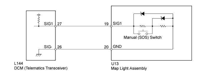
| 1.READ VALUE USING TECHSTREAM (MANUAL (SOS) SWITCH OPERATION) |
Turn the power switch off.
Connect the Techstream to the DLC3.
Turn the power switch on (IG) and wait for 10 seconds.
Turn the Techstream on.
Enter the following menus: Body Electrical / Telematics / Data List.
Check that the manual (SOS) switch condition observed on the Techstream changes according to manual (SOS) switch operation.
| Tester Display | Measurement Item/Range | Normal Condition | Diagnostic Note |
| Emergency Switch | Manual (SOS) switch / OFF or ON | OFF: Manual (SOS) switch not pressed | - |
| ON: Manual (SOS) switch pressed | - |
| Result | Proceed to |
| Techstream display changes when turning the manual (SOS) switch ON/OFF. | A |
| Techstream display does not change when turning the manual (SOS) switch ON/OFF. | B |
|
| ||||
| A | |
 |
| 2.REPLACE DCM (TELEMATICS TRANSCEIVER) |
Replace the DCM (Telematics Transceiver) (Click here).
| NEXT | ||
 | ||
| ||
| 3.INSPECT DCM (TELEMATICS TRANSCEIVER) (SIG1 VOLTAGE) |
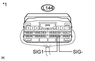 |
Remove the DCM (Telematics Transceiver) but do not disconnect the connectors (Click here).
Measure the voltage according to the value(s) in the table below.
| Tester Connection | Condition | Specified Condition |
| L144-27 (SIG1) - L144-26 (SIG-) | Power switch on (IG), manual (SOS) switch not pressed | 1.5 to 2.0 V |
| *1 | Component with harness connected (DCM (Telematics Transceiver)) |
|
| ||||
| OK | |
|
| 4.REPLACE DCM (TELEMATICS TRANSCEIVER) |
Replace the DCM (Telematics Transceiver) (Click here).
| NEXT | ||
| ||
| ||
| 5.INSPECT MAP LIGHT ASSEMBLY (MANUAL (SOS) SWITCH) |
Disconnect the U3*1 or U13*2 map light assembly connector.
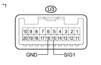 |
w/o Sliding Roof:
Measure the resistance according to the value(s) in the table below.
| Tester Connection | Condition | Specified Condition |
| U3-15 (SIG1) - U3-16 (GND) | Manual (SOS) switch not pressed | 410 to 414 Ω |
| U3-15 (SIG1) - U3-16 (GND) | Manual (SOS) switch pressed | 81 to 83 Ω |
| *1 | Component without harness connected (Map Light Assembly) |
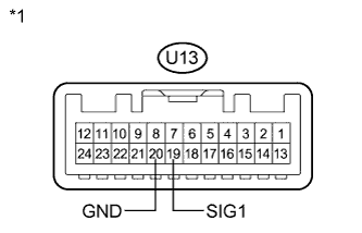 |
w/ Sliding Roof:
Measure the resistance according to the value(s) in the table below.
| Tester Connection | Condition | Specified Condition |
| U13-19 (SIG1) - U13-20 (GND) | Manual (SOS) switch not pressed | 410 to 414 Ω |
| U13-19 (SIG1) - U13-20 (GND) | Manual (SOS) switch pressed | 81 to 83 Ω |
| *1 | Component without harness connected (Map Light Assembly) |
|
| ||||
| OK | |
|
| 6.CHECK HARNESS AND CONNECTOR (DCM (TELEMATICS TRANSCEIVER) - MAP LIGHT ASSEMBLY) |
Disconnect the L144 DCM (Telematics Transceiver) connector.
Disconnect the U3*1 or U13*2 map light assembly connector.
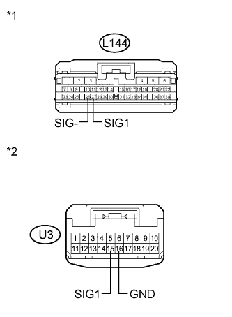 |
w/o Sliding Roof:
Measure the resistance according to the value(s) in the table below.
| Tester Connection | Condition | Specified Condition |
| L144-27 (SIG1) - U3-15 (SIG1) | Always | Below 1 Ω |
| L144-26 (SIG-) - U3-16 (GND) | Always | Below 1 Ω |
| L144-27 (SIG1) - Body ground | Always | 10 kΩ or higher |
| L144-26 (SIG-) - Body ground | Always | 10 kΩ or higher |
| *1 | Front view of wire harness connector (to DCM (Telematics Transceiver)) |
| *2 | Front view of wire harness connector (to Map Light Assembly) |
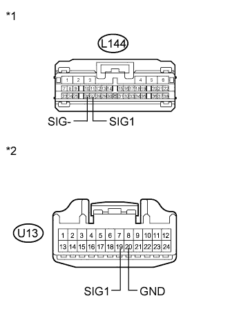 |
w/ Sliding Roof:
Measure the resistance according to the value(s) in the table below.
| Tester Connection | Condition | Specified Condition |
| L144-27 (SIG1) - U13-19 (SIG1) | Always | Below 1 Ω |
| L144-26 (SIG-) - U13-20 (GND) | Always | Below 1 Ω |
| L144-27 (SIG1) - Body ground | Always | 10 kΩ or higher |
| L144-26 (SIG-) - Body ground | Always | 10 kΩ or higher |
| *1 | Front view of wire harness connector (to DCM (Telematics Transceiver)) |
| *2 | Front view of wire harness connector (to Map Light Assembly) |
|
| ||||
| OK | |
|
| 7.REPLACE DCM (TELEMATICS TRANSCEIVER) |
Replace the DCM (Telematics Transceiver) (Click here).
| NEXT | ||
| ||
| ||

