 |
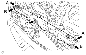
Temporarily install the upper radiator support sub-assembly with the 5 bolts.
RADIATOR > INSTALLATION |
| 1. INSTALL RADIATOR ASSEMBLY |
Install the radiator assembly with the 2 claws.
Install the No. 3 radiator hose with the 2 bolts.
Install the 2 lower radiator supports.
Install the radiator assembly with the fan shroud.
| 2. INSTALL NO. 2 FAN SHROUD |
Install the No. 2 fan shroud with the 2 bolts and 2 claws.
| 3. INSTALL UPPER RADIATOR SUPPORT SUB-ASSEMBLY |
Install the 2 radiator support cushions.
|
Temporarily install the upper radiator support sub-assembly with the 5 bolts.
Fully tighten the bolt (A).
Fully tighten the bolt (B).
Fully tighten the bolt (C).
Connect the clamp of the hood lock control cable.
Connect the cooling fan ECU connector and 3 clamps.
Connect the horn connector.
| 4. CONNECT NO. 1 INVERTER COOLING HOSE ASSEMBLY |
Connect the No. 1 inverter cooling hose assembly and 3 clamps.
| 5. CONNECT OUTLET NO. 1 HYBRID WATER PUMP HOSE |
Connect the outlet No. 1 hybrid water pump hose and 3 clamps.
| 6. CONNECT NO. 2 RADIATOR HOSE |
Connect the No. 2 radiator hose.
| 7. CONNECT NO. 1 RADIATOR HOSE |
Connect the No. 1 radiator hose.
Connect the reserve tank hose.
| 8. INSTALL HOOD LOCK ASSEMBLY |
Apply MP grease to the sliding areas of the hood lock assembly.
Connect the hood lock control cable.
Install the hood lock with the 3 bolts.
| 9. INSTALL AIR CLEANER CASE SUB-ASSEMBLY |
Install the air cleaner case sub-assembly with the 2 bolts and grommet.
Install the air cleaner filter element sub-assembly.
| 10. INSTALL AIR CLEANER CAP SUB-ASSEMBLY |
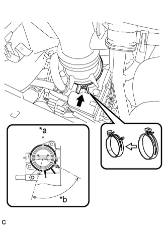 |
Install the air cleaner hose sub-assembly and lock the hose clamp.
| *a | Engine Side |
| *b | 75° |
Install the air cleaner cap sub-assembly with the 2 clamps.
Connect the wire harness clamp.
Connect the mass air flow meter connector.
Connect the purge VSV.
Connect the ventilation hose.
| 11. INSTALL RADIATOR SUPPORT OPENING COVER |
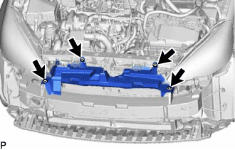 |
Install the radiator support opening cover with the 4 clips.
| 12. INSTALL FRONT BUMPER ASSEMBLY |
| 13. CONNECT CABLE TO NEGATIVE AUXILIARY BATTERY TERMINAL |
| 14. INSTALL FRONT FLOOR COVER RH |
Engage the 3 guides.
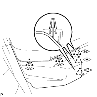 |
Engage the clip <B> to install the front floor cover RH.
Install the 2 clips <A>.
| 15. ADD COOLANT (for Inverter) |
| DTC Code | Detection Item |
| P0A01-726 | Motor Electronics Coolant Temperature Sensor Circuit Range / Performance |
| P0A04-725 | Motor Electronics Coolant Temperature Sensor Circuit Intermittent |
| P0A08-264 | DC / DC Converter Status Circuit |
| P0A78-284 | Drive Motor "A" Inverter Performance |
| P0A78-286 | Drive Motor "A" Inverter Performance |
| P0A7A-322 | Generator Inverter Performance |
| P0A7A-324 | Generator Inverter Performance |
| P0A93-346 | Inverter Cooling System Performance |
| P0A94-553 | DC / DC Converter Performance |
| P0A94-557 | DC / DC Converter Performance |
| P0AEE-277 | Motor Inverter Temperature Sensor "A" Circuit Range / Performance |
| P0AF1-276 | Drive Motor Inverter Temperature Sensor "A" Circuit Intermittent / Erratic |
| P0BCD-315 | Generator Inverter Temperature Sensor Circuit Range / Performance |
| P0BD0-314 | Generator Inverter Temperature Sensor Circuit Intermittent / Erratic |
| P0C39-626 | DC / DC Converter Temperature Sensor "A" Range / Performance |
| P0C3C-625 | DC / DC Converter Temperature Sensor "A" Intermittent / Erratic |
| P0C3E-628 | DC / DC Converter Temperature Sensor "B" Range / Performance |
| P0C41-627 | DC / DC Converter Temperature Sensor "B" Intermittent / Erratic |
| P0C73-776 | Motor Electronics Coolant Pump "A" Control Performance |
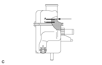 |
Slowly pour coolant into the reserve tank until it reaches the full line.
When using the intelligent tester:
Connect the intelligent tester to the DLC3.
Turn the power switch on (IG).
Enter the following menus: Powertrain / Hybrid Control / Active Test / Activate the Water Pump.
Keep the coolant at the full line in the reserve tank to compensate for the drop in coolant level when the air bleeds.
When not using the intelligent tester:
Turn the power switch on (READY). [*1]
Turn the power switch off and add coolant to the full line because the coolant level drops as the air bleeds. [*2]
Repeat steps [*1] and [*2] until air bleeding from the cooling system is completed.
After the air is completely bled from the cooling system, tighten the reserve tank cap.
|
Add coolant to the full line of the reserve tank.
| 16. ADD COOLANT (for Engine) |
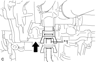 |
Insert the engine drain cock plug.
| *1 | Hose |
Disconnect the hose from the engine drain cock plug.
Install the stop ring.
Tighten the radiator drain cock plug by hand.
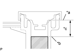 |
Slowly fill the radiator with TOYOTA Super Long Life Coolant (SLLC) from the water filler. (Coolant level should be within 20 mm (0.787 in.) from the filler tube end.)
| *a | Filler Tube End |
| *b | Coolant Level |
| *c | 20 mm |
Remove the reserve tank cap.
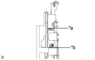 |
Slowly pour coolant into the radiator reserve tank assembly until it reaches the full line.
| *a | Full Line |
| *b | Low Line |
Squeeze the No. 1 and No. 2 radiator hoses several times by hand, and then check the level of the coolant.
If the coolant level is low, add coolant.
Install the water filler cap sub-assembly and reserve tank cap.
Put the engine in inspection mode (Click here).
Bleed air from the cooling system.
Warm up the engine until the thermostat opens. While the thermostat is open, circulate the coolant for several minutes.
Squeeze the No. 1 and No. 2 radiator hoses several times by hand to bleed air.
Stop the engine and wait until the engine coolant cools down.
Add engine coolant to the full line on the radiator reserve tank assembly.
| 17. INSPECT FOR COOLANT LEAK (for Inverter) |
Remove the reserve tank cap.
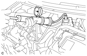 |
Install a radiator cap tester.
Pump the radiator cap tester to 122 kPa (1.2 kgf/ cm2, 18 psi), and then check that the pressure does not drop.
Reinstall the reserve tank cap.
| 18. INSPECT FOR COOLANT LEAK (for Engine) |
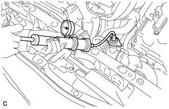 |
Fill the radiator with coolant and attach a radiator cap tester.
Put the engine in inspection mode (Click here).
Warm up the engine.
Using a radiator cap tester, increase the pressure inside the radiator to 108 kPa (1.1 kgf/cm2, 16 psi), and check that the pressure does not drop.
If the pressure drops, check the hoses, radiator, engine water pump, front exhaust pipe assembly and engine coolant temperature sensor for leaks. If no external leaks are found, check the heater core, cylinder block and cylinder head.
| 19. INSTALL ENGINE UNDER COVER RH |
| 20. INSTALL ENGINE UNDER COVER LH |