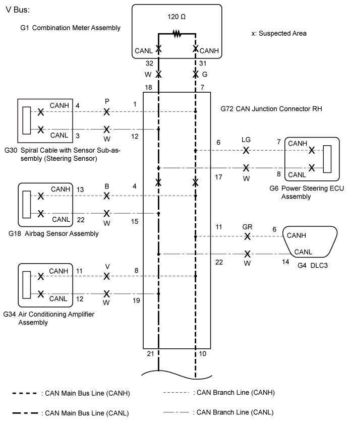
CAN COMMUNICATION SYSTEM > Check CAN Bus Lines for Short Circuit (RHD Models) |
| Symptom | Trouble Area |
| Resistance between terminals 6 (CANH) and 14 (CANL) of the DLC3 is below 54 Ω. |
|
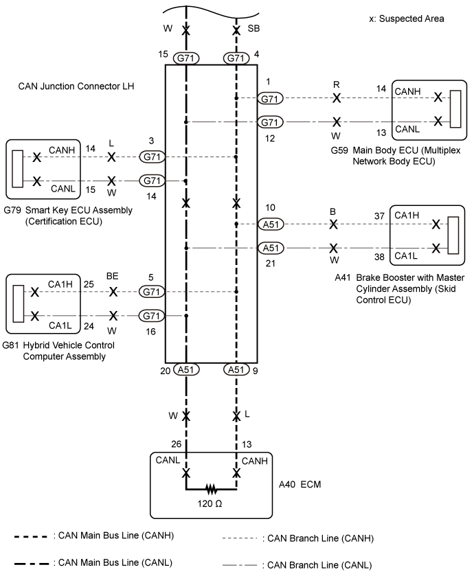
| 1.CHECK FOR SHORT IN CAN BUS LINES (COMBINATION METER ASSEMBLY - CAN J/C RH) |
Disconnect the cable from the negative (-) auxiliary battery terminal.
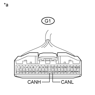 |
Disconnect the G1 combination meter assembly connector.
Measure the resistance according to the value(s) in the table below.
| Tester Connection | Condition | Specified Condition |
| G1-31 (CANH) - G1-32 (CANL) | Cable disconnected from negative (-) auxiliary battery terminal | 108 to 132 Ω |
| *a | Front view of wire harness connector (to Combination Meter Assembly) |
|
| ||||
| OK | ||
 | ||
| ||
| 2.CHECK FOR SHORT IN CAN BUS LINES (ECM MAIN BUS LINE - CAN J/C LH) |
Reconnect the G1 combination meter assembly connector.
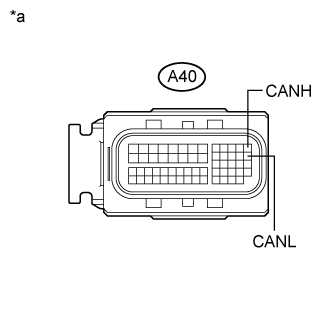 |
Disconnect the A40 ECM connector.
Measure the resistance according to the value(s) in the table below.
| Tester Connection | Condition | Specified Condition |
| A40-13 (CANH) - A40-26 (CANL) | Cable disconnected from negative (-) auxiliary battery terminal | 108 to 132 Ω |
| *a | Front view of wire harness connector (to ECM) |
|
| ||||
| OK | ||
| ||
| ||
| 3.CHECK FOR SHORT IN CAN BUS LINES (CAN J/C RH) |
Reconnect the A40 ECM connector.
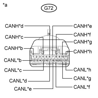 |
Disconnect the G72 CAN junction connector RH.
Measure the resistance according to the value(s) in the table below.
| Tester Connection | Condition | Specified Condition | Connected to |
| G72-1 (CANH) - G72-12 (CANL) | Cable disconnected from negative (-) auxiliary battery terminal | 200 Ω or higher | Spiral cable with sensor sub-assembly (Steering sensor) |
| G72-4 (CANH) - G72-15 (CANL) | Cable disconnected from negative (-) auxiliary battery terminal | 200 Ω or higher | Airbag sensor assembly |
| G72-6 (CANH) - G72-17 (CANL) | Cable disconnected from negative (-) auxiliary battery terminal | 200 Ω or higher | Power steering ECU assembly |
| G72-7 (CANH) - G72-18 (CANL) | Cable disconnected from negative (-) auxiliary battery terminal | 108 to 132 Ω | Combination meter assembly |
| G72-8 (CANH) - G72-19 (CANL) | Cable disconnected from negative (-) auxiliary battery terminal | 200 Ω or higher | Air conditioning amplifier assembly |
| G72-10 (CANH) - G72-21 (CANL) | Cable disconnected from negative (-) auxiliary battery terminal | 108 to 132 Ω | CAN junction connector LH |
| G72-11 (CANH) - G72-22 (CANL) | Cable disconnected from negative (-) auxiliary battery terminal | 1 MΩ or higher | DLC3 |
| *a | Front view of wire harness connector (to CAN Junction Connector RH) |
| *b | to Spiral Cable with Sensor Sub-assembly (Steering Sensor) |
| *c | to Airbag Sensor Assembly |
| *d | to Power Steering ECU Assembly |
| *e | to Combination Meter Assembly |
| *f | to Air Conditioning Amplifier Assembly |
| *g | to CAN Junction Connector LH |
| *h | to DLC3 |
| Result | Proceed to |
| OK | A |
| NG (CAN junction connector LH main lines) | B |
| NG (ECU or sensor branch lines) | C |
| NG (Combination meter assembly main lines) | D |
| NG (DLC3 branch lines) | E |
|
| ||||
|
| ||||
|
| ||||
|
| ||||
| A | ||
| ||
| ||
| 4.CHECK FOR SHORT IN CAN BUS LINES (CAN J/C LH (INSTRUMENT PANEL WIRE SIDE)) |
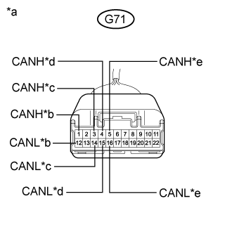 |
Disconnect the G71 CAN junction connector LH (instrument panel wire side).
Measure the resistance according to the value(s) in the table below.
| Tester Connection | Condition | Specified Condition | Connected to |
| G71-1 (CANH) - G71-12 (CANL) | Cable disconnected from negative (-) auxiliary battery terminal | 200 Ω or higher | Main body ECU (Multiplex network body ECU) |
| G71-3 (CANH) - G71-14 (CANL) | Cable disconnected from negative (-) auxiliary battery terminal | 200 Ω or higher | Smart key ECU assembly (Certification ECU) |
| G71-4 (CANH) - G71-15 (CANL) | Cable disconnected from negative (-) auxiliary battery terminal | 1 MΩ or higher | CAN junction connector RH |
| G71-5 (CANH) - G71-16 (CANL) | Cable disconnected from negative (-) auxiliary battery terminal | 200 Ω or higher | Hybrid vehicle control computer assembly |
| *a | Front view of wire harness connector (to CAN Junction Connector LH (Instrument Panel Wire Side)) |
| *b | to Main Body ECU (Multiplex Network Body ECU) |
| *c | to Smart Key ECU Assembly (Certification ECU) |
| *d | to CAN Junction Connector RH |
| *e | to Hybrid Vehicle Control Computer Assembly |
| Result | Proceed to |
| OK | A |
| NG (CAN junction connector RH main lines) | B |
| NG (ECU or sensor branch lines) | C |
|
| ||||
|
| ||||
| A | |
 |
| 5.CHECK FOR SHORT IN CAN BUS LINES (CAN J/C LH (ENGINE ROOM MAIN WIRE SIDE)) |
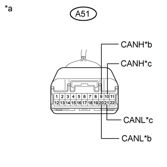 |
Disconnect the A51 CAN junction connector LH (engine room main wire side).
Measure the resistance according to the value(s) in the table below.
| Tester Connection | Condition | Specified Condition | Connected to |
| A51-9 (CANH) - A51-20 (CANL) | Cable disconnected from negative (-) auxiliary battery terminal | 108 to 132 Ω | ECM |
| A51-10 (CANH) - A51-21 (CANL) | Cable disconnected from negative (-) auxiliary battery terminal | 200 Ω or higher | Brake booster with master cylinder assembly (Skid control ECU) |
| *a | Front view of wire harness connector (to CAN Junction Connector LH (Engine Room Main Wire Side)) |
| *b | to ECM |
| *c | to Brake Booster with Master Cylinder Assembly (Skid Control ECU) |
| Result | Proceed to |
| OK | A |
| NG (ECM main lines) | B |
| NG (ECU or sensor branch lines) | C |
|
| ||||
|
| ||||
| A | ||
| ||
| ||
| 6.CHECK FOR SHORT IN CAN BUS LINES (ECU, SENSOR) |
Reconnect all wire harness connectors (CAN junction connector LH and CAN junction connector RH).
Disconnect the connector that includes terminals CANH and CANL from the ECU or sensor to which the short circuited branch line is connected (Click here).
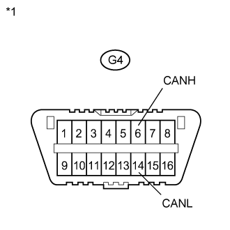 |
Measure the resistance according to the value(s) in the table below.
| Tester Connection | Condition | Specified Condition |
| G4-6 (CANH) - G4-14 (CANL) | Cable disconnected from negative (-) auxiliary battery terminal | 54 to 69 Ω |
| *1 | DLC3 |
|
| ||||
| OK | ||
| ||
| ||

