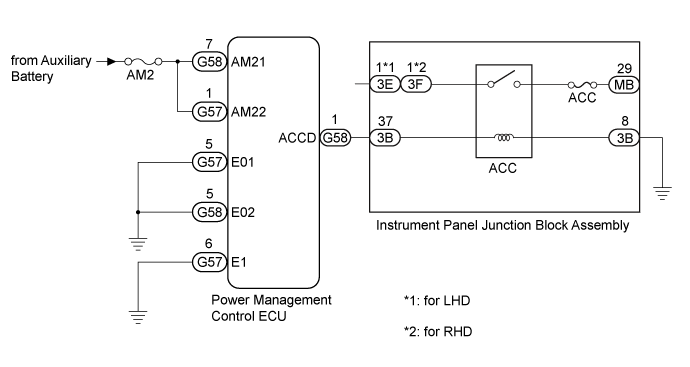
DTC B2274 ACC Monitor Malfunction |
| DTC Code | DTC Detection Condition | Trouble Area | DTC Output Confirmation Operation |
| B2274 | Malfunction in the ACC relay circuit in the power management control ECU or in the external circuit (1-trip detection logic*).
|
| Wait 10 seconds after turning the power switch on (ACC) or on (IG), and then wait another 10 seconds after turning the power switch off. |
| Vehicle Condition when Malfunction Detected | Fail-safe Function when Malfunction Detected |
| - |
| DTC | Data List Item | Active Test Item |
| B2274 | Power Source Control
| - |
| 1.CHECK HARNESS AND CONNECTOR (POWER SOURCE) |
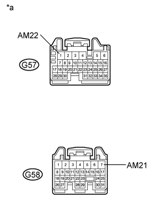 |
Disconnect the G57 and G58 connectors from the power management control ECU.
Measure the voltage according to the value(s) in the table below.
| Tester Connection | Condition | Specified Condition |
| G57-1 (AM22) - Body ground | Power switch off | 11 to 14 V |
| G58-7 (AM21) - Body ground | Power switch off | 11 to 14 V |
| *a | Front view of wire harness connector (to Power Management Control ECU) |
|
| ||||
| OK | |
 |
| 2.CHECK HARNESS AND CONNECTOR (GROUND) |
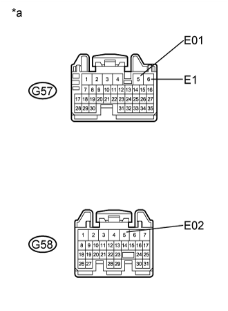 |
Measure the resistance according to the value(s) in the table below.
| Tester Connection | Condition | Specified Condition |
| G57-5 (E01) - Body ground | Always | Below 1 Ω |
| G57-6 (E1) - Body ground | Always | Below 1 Ω |
| G58-5 (E02) - Body ground | Always | Below 1 Ω |
| *a | Front view of wire harness connector (to Power Management Control ECU) |
|
| ||||
| OK | |
|
| 3.CHECK HARNESS AND CONNECTOR (POWER MANAGEMENT CONTROL ECU - INSTRUMENT PANEL JUNCTION BLOCK ASSEMBLY) |
Disconnect the G58 connector from the power management control ECU.
Disconnect the 3B connector from the instrument panel junction block assembly.
Measure the resistance according to the value(s) in the table below.
| Tester Connection | Condition | Specified Condition |
| G58-1 (ACCD) - 3B-37 | Always | Below 1 Ω |
| 3B-8 - Body ground | Always | Below 1 Ω |
| G58-1 (ACCD) or 3B-37 - Body ground | Always | 10 kΩ or higher |
|
| ||||
| OK | |
|
| 4.CHECK INSTRUMENT PANEL JUNCTION BLOCK ASSEMBLY (ACC RELAY) |
Remove the instrument panel junction block assembly (Click here).
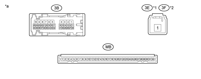
| *1 | for LHD | *2 | for RHD |
| *a | Component without harness connected (Instrument Panel Junction Block Assembly) | - | - |
Remove the main body ECU (multiplex network body ECU) from the instrument panel junction block assembly (Click here).
Measure the resistance according to the value(s) in the table below.
| Tester Connection | Condition | Specified Condition |
| 3E-1 - MB-29*1 3F-1 - MB-29*2 | Auxiliary battery voltage not applied to terminals 3B-37 and 3B-8 | 10 kΩ or higher |
| Auxiliary battery voltage applied to terminals 3B-37 and 3B-8 | Below 1 Ω |
|
| ||||
| OK | |
|
| 5.INSPECT POWER MANAGEMENT CONTROL ECU |
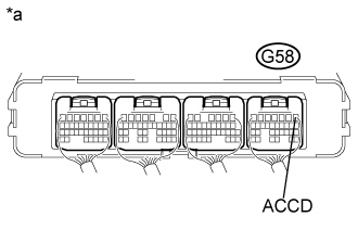 |
Reconnect the G58 power management control ECU connector.
Measure the voltage according to the value(s) in the table below.
| Tester Connection | Condition | Specified Condition |
| G58-1 (ACCD) - Body ground | Power switch off → Power switch on (ACC) | 1 V or less → 8.5 V or higher |
| *a | Component with harness connected (Power Management Control ECU) |
|
| ||||
| OK | ||
 | ||
| ||
