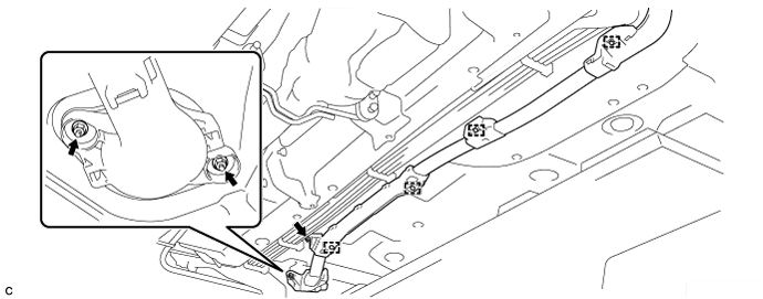
Install a frame wire with the 4 new clamps as shown in the illustration.
FRAME WIRE > INSTALLATION |
| 1. INSTALL FRAME WIRE |
Install a frame wire with the 4 new clamps as shown in the illustration.
Insert the frame wire into the floor panel hole.
Install the 3 nuts as shown in the illustration.
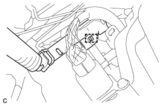 |
Connect the clamp as shown in the illustration.
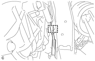 |
Connect the clamp as shown in the illustration.
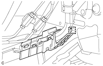 |
Connect the clamp as shown in the illustration.
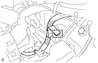 |
Connect the clamp as shown in the illustration.
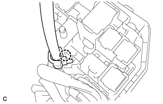 |
Connect the frame wire with the claw as shown in the illustration.
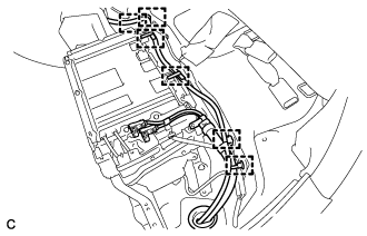 |
Connect the 6 clamps as shown in the illustration.
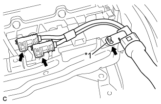 |
Connect the 2 connectors to the engine room junction block assembly as shown in the illustration.
| *1 | Shielded Wire Ground |
Connect the shielded wire ground as shown in the illustration.
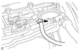 |
Connect the connector.
| 2. CONNECT CABLE TO POSITIVE AUXILIARY BATTERY TERMINAL |
Connect the positive auxiliary battery terminal with the nut.
Install the terminal cover.
| 3. INSTALL NO. 1 HYBRID BATTERY EXHAUST DUCT |
Install the No. 1 hybrid battery exhaust duct with the clip.
| 4. INSTALL NO. 1 HYBRID VEHICLE BATTERY COVER PANEL LH |
Install the No. 1 hybrid vehicle battery cover panel LH with the 4 nuts.
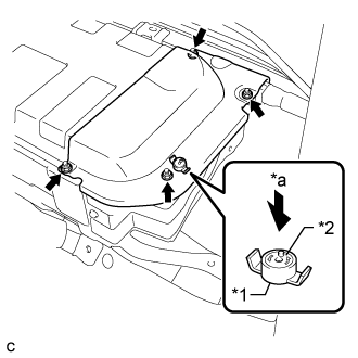 |
Install the battery cover lock striker, then push the button to lock it.
| *1 | Battery Cover Lock Striker |
| *2 | Button |
| *a | Push |
| 5. INSTALL BATTERY COOLING BLOWER ASSEMBLY |
Install the battery cooling blower assembly with the 2 bolts and nut.
Connect the battery cooling blower assembly connector and engage the clamp to the battery cooling blower assembly.
| 6. INSTALL REAR SEAT CUSHION LEG SUB-ASSEMBLY |
Temporarily install the rear seat cushion leg sub-assembly with the 4 bolts.
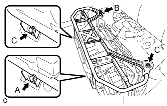 |
Tighten the bolt (A).
Tighten the bolt (B).
Tighten the 2 bolts (C).
| 7. INSTALL REAR SEAT CUSHION ASSEMBLY |
Place the rear seat cushion assembly in the cabin.
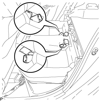 |
Push out the seat belt buckles from the back of the rear seat cushion assembly so that they are positioned as shown in the illustration.
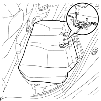 |
Engage the hook of the rear seat cushion assembly to the CRS anchor bracket.
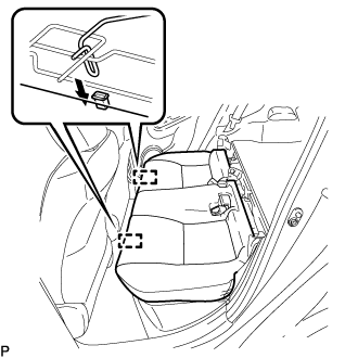 |
Engage the 2 rear seat cushion lock hooks to install the rear seat cushion assembly as shown in the illustration.
Confirm that the seat cushion is firmly installed.
Engage the 2 clips.
| 8. INSTALL FRONT SUSPENSION CROSSMEMBER SUB-ASSEMBLY |
| 9. INSTALL INVERTER BRACKET ASSEMBLY |
Temporarily install the inverter bracket assembly with the 4 bolts.
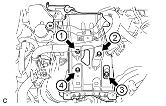 |
Tighten the 4 bolts in the sequence shown in the illustration.
Connect the earth wire with the bolt.
Install the inverter reservoir tank assembly with the 2 bolts.
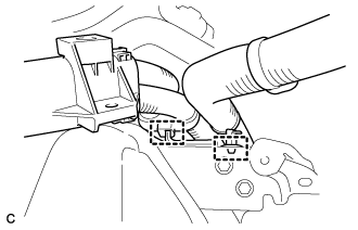 |
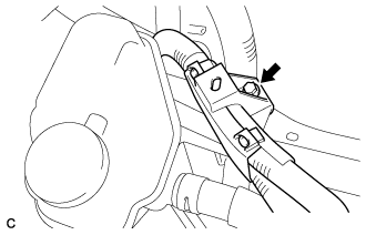
Connect the 2 wire harness clamps.
 |
Connect the motor cable protector with the bolt.
| 10. INSTALL INVERTER WITH CONVERTER ASSEMBLY |