Home › Engine / Hybrid System › 1NZ-FXE ENGINE CONTROL › ECM

ECM > INSTALLATION

for Preparation Click here


1. INSTALL ECM (for LHD)
  1. Install the No. 1 ECM bracket and No. 2 ECM bracket with the 4 screws.

    Torque:
    4.5 N*m{ 46 kgf*cm , 40 in.*lbf }

  1. Install the nut.

    Torque:
    8.0 N*m{ 82 kgf*cm , 71 in.*lbf }

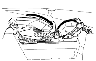
  1. Install the ECM with the bolt and nut.

    Torque:
    8.0 N*m{ 82 kgf*cm , 71 in.*lbf }


    A275536
  1. Connect the 2 ECM connectors and lower the 2 levers.

    NOTICE:
    1. When connecting the ECM connectors, make sure that the connecting parts of the ECM connectors are free of dirt, water or other foreign matter.
    2. Be sure to securely connect the ECM connectors.


2. INSTALL OUTER COWL TOP PANEL SUB-ASSEMBLY (for LHD)


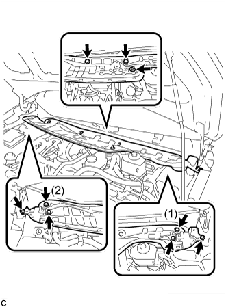
    C250015E01
  1. Install the outer cowl top panel sub-assembly with the 8 bolts and nut.

    Torque:
    Bolt:
    7.0 N*m{ 71 kgf*cm , 62 in.*lbf }
    Nut:
    12 N*m{ 122 kgf*cm , 9 ft.*lbf }

    NOTICE:
    Tighten the 2 bolts (1) and (2) first, and then tighten the rest of the bolts and nut.

  1. Engage the clamp to install the wire harness.


3. INSTALL FRONT NO. 1 VENTILATOR SEAL (for LHD)
  1. Engage the clamp to install the front No. 1 ventilator seal to the outer cowl top panel sub-assembly.


4. INSTALL FRONT AIR SHUTTER SEAL (for LHD)
  1. Engage the clamp to install the front air shutter seal to the outer cowl top panel sub-assembly.


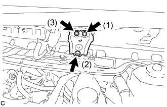
5. INSTALL INNER COWL TOP TO COWL BRACE (for LHD)


    C250011E01
  1. Install the inner cowl top to cowl brace to the outer cowl top panel sub-assembly with the 3 bolts.

    Torque:
    7.0 N*m{ 71 kgf*cm , 62 in.*lbf }

    NOTICE:
    Tighten the 3 bolts in the order shown in the illustration.


6. INSTALL WINDSHIELD WIPER MOTOR AND LINK ASSEMBLY (for LHD)
(Click here).


7. INSTALL ECM (for RHD)
  1. Install the No. 1 ECM bracket and No. 2 ECM bracket with the 4 screws.

    Torque:
    4.5 N*m{ 46 kgf*cm , 40 in.*lbf }

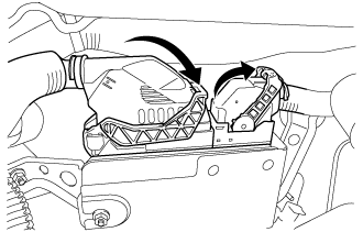
  1. Install the ECM with the bolt and nut.

    Torque:
    8.0 N*m{ 82 kgf*cm , 71 in.*lbf }


    A275537
  1. Connect the 2 ECM connectors and lower the 2 levers.

    NOTICE:
    1. When connecting the ECM connectors, make sure that the connecting parts of the ECM connectors are free of dirt, water or other foreign matter.
    2. Be sure to securely connect the ECM connectors.


8. CONNECT CABLE TO NEGATIVE AUXILIARY BATTERY TERMINAL

NOTICE:
When disconnecting the cable, some systems need to be initialized after the cable is reconnected (Click here).


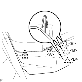
9. INSTALL FRONT FLOOR COVER RH
  1. Engage the 3 guides.


    B301488E01
  1. Engage the clip <B> to install the front floor cover RH.

  1. Install the 2 clips <A>.


10. PERFORM INITIALIZATION

HINT:
Initialization cannot be completed by only disconnecting and reconnecting the cable of the negative (-) auxiliary battery terminal.

  1. Perform Initialization when replacing the ECM .