 |
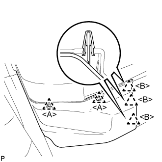
Using a clip remover, remove the 2 clips <A>.
FUEL INJECTOR > REMOVAL |
| 1. PRECAUTION |
| 2. DISCHARGE FUEL SYSTEM PRESSURE |
| 3. REMOVE FRONT FLOOR COVER RH |
|
Using a clip remover, remove the 2 clips <A>.
Disengage the 3 clips <B>.
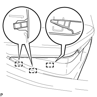 |
Disengage the 3 guides and remove the front floor cover RH.
| 4. DISCONNECT CABLE FROM NEGATIVE AUXILIARY BATTERY TERMINAL |
| 5. REMOVE EGR VALVE WITH COOLER ASSEMBLY |
| 6. SEPARATE BRAKE MASTER CYLINDER RESERVOIR ASSEMBLY (for RHD) |
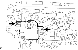 |
Remove the 2 nuts and separate the brake master cylinder reservoir assembly from the reservoir bracket.
| 7. REMOVE NO. 1 IGNITION COIL |
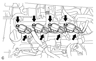 |
Disconnect the 4 No. 1 ignition coil connectors.
Remove the 4 bolts and 4 No. 1 ignition coils.
| 8. SEPARATE ENGINE WIRE (for LHD) |
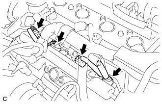 |
Disconnect the 4 injector connectors.
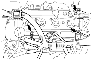 |
Disconnect the wire harness clamp.
Remove the 3 bolts and separate the engine wire.
| 9. SEPARATE ENGINE WIRE (for RHD) |
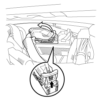 |
Push the lock on the lever, then raise the lever, and disconnect the ECM connector.
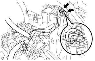 |
Disconnect the 2 connectors and wire harness clamp.
Using a screwdriver, disengage the claw and disconnect the engine wire from the engine room relay block and junction block assembly.
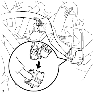 |
Disconnect the engine wire from the engine room main wire.
Disconnect the wire harness clamp.
| 10. REMOVE CYLINDER HEAD COVER SUB-ASSEMBLY |
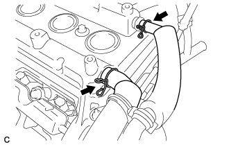 |
Disconnect the No. 1 ventilation hose and No. 2 ventilation hose.
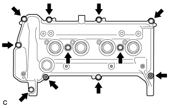 |
Remove the 9 bolts, 2 seal washers, 2 nuts and cylinder head cover sub-assembly.
Remove the gasket from the cylinder head cover sub-assembly.
| 11. REMOVE EFI FUEL PIPE CLAMP |
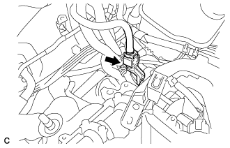 |
Remove the EFI fuel pipe clamp.
| 12. DISCONNECT FUEL TUBE SUB-ASSEMBLY |
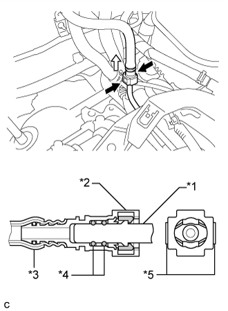 |
Pinch the retainer of the fuel tube connector, and then pull the fuel tube connector off of the fuel delivery pipe.
| *1 | Fuel delivery pipe |
| *2 | Fuel Tube Connector |
| *3 | Nylon Tube |
| *4 | O-ring |
| *5 | Retainer |
 | Pinch |
 | Pull |
| 13. REMOVE FUEL DELIVERY PIPE |
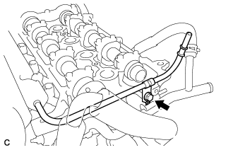 |
Remove the bolt.
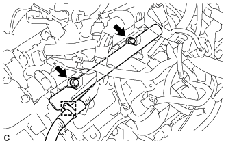 |
Disengage the clamp to disconnect the wire harness.
Remove the 2 bolts and the fuel delivery pipe with the 4 fuel injectors.
| 14. REMOVE FUEL DELIVERY SPACER |
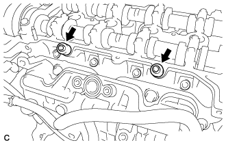 |
Remove the 2 fuel delivery spacers from the cylinder head.
| 15. REMOVE INJECTOR VIBRATION INSULATOR |
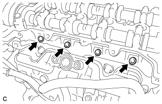 |
Remove the 4 injector vibration insulators from the cylinder head.
| 16. REMOVE FUEL INJECTOR ASSEMBLY |
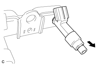 |
Pull the 4 fuel injector assemblies out of the fuel delivery pipe.
| Pull |
Remove the O-ring from each fuel injector.
For reinstallation, attach a tag or label to each injector shaft.