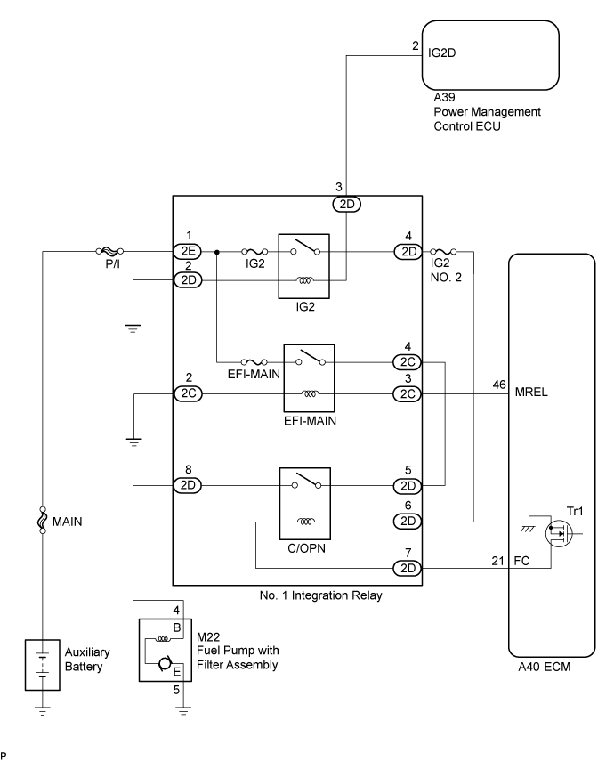
SFI SYSTEM > Fuel Pump Control Circuit |
| 1.PERFORM ACTIVE TEST USING INTELLIGENT TESTER (CONTROL THE FUEL PUMP / SPEED) |
Connect the intelligent tester to the DLC3.
Turn the power switch on (IG).
Turn the tester on.
Enter the following menus: Powertrain / Engine and ECT / Active Test / Control the Fuel Pump / Speed.
Check whether the fuel pump with filter assembly operating sound occurs when performing the Active Test on the tester.
| Result | Proceed to |
| Fuel pump with filter assembly operating sound does not occur | A |
| Fuel pump with filter assembly operating sound occurs | B |
|
| ||||
| A | |
 |
| 2.CHECK HARNESS AND CONNECTOR (NO. 1 INTEGRATION RELAY - ECM) |
Remove the No. 1 integration relay from the No. 2 engine room relay block and No. 2 junction block assembly.
Disconnect the ECM connector.
Measure the resistance according to the value(s) in the table below.
| Tester Connection | Condition | Specified Condition |
| 2D-7 - A40-21 (FC) | Always | Below 1 Ω |
| 2D-7 or A40-21 (FC) - Body ground | Always | 10 kΩ or higher |
|
| ||||
| OK | |
|
| 3.CHECK HARNESS AND CONNECTOR (NO. 1 INTEGRATION RELAY - FUEL PUMP WITH FILTER ASSEMBLY) |
Remove the No. 1 integration relay from the No. 2 engine room relay block and No. 2 junction block assembly.
Disconnect the fuel pump with filter assembly connector.
Measure the resistance according to the value(s) in the table below.
| Tester Connection | Condition | Specified Condition |
| 2D-8 - M22-4 (B) | Always | Below 1 Ω |
| 2D-8 or M22-4 (B) - Body ground | Always | 10 kΩ or higher |
|
| ||||
| OK | |
|
| 4.CHECK HARNESS AND CONNECTOR (FUEL PUMP WITH FILTER ASSEMBLY - BODY GROUND) |
Disconnect the fuel pump with filter assembly connector.
Measure the resistance according to the value(s) in the table below.
| Tester Connection | Condition | Specified Condition |
| M22-5 (E) - Body ground | Always | Below 1 Ω |
|
| ||||
| OK | |
|
| 5.INSPECT FUEL PUMP WITH FILTER ASSEMBLY |
Inspect the fuel pump with filter assembly (Click here).
|
| ||||
| OK | |
|
| 6.INSPECT NO.1 INTEGRATION RELAY (C/OPN RELAY) |
Inspect the No. 1 integration relay (C/OPN relay) (Click here).
|
| ||||
| OK | ||
 | ||
| ||
| 7.READ VALUE USING INTELLIGENT TESTER (STARTER SIGNAL) |
Connect the intelligent tester to the DLC3.
Turn the power switch on (IG).
Turn the tester on.
Put the engine in inspection mode (maintenance mode) (Click here).
Enter the following menus: Powertrain / Engine and ECT / Data List / All Data / Starter Signal.
Check the result when the power switch on (IG) and the engine starts.
| Condition | Starter Signal |
| Power switch on (IG) | Close (OFF) |
| Engine started | Open (ON) |
|
| ||||
| OK | |
|
| 8.READ VALUE USING INTELLIGENT TESTER (ENGINE SPEED) |
Connect the intelligent tester to the DLC3.
Turn the power switch on (IG).
Turn the tester on.
Put the engine in inspection mode (maintenance mode) (Click here).
Enter the following menus: Powertrain / Engine and ECT / Data List / All Data / Engine Speed.
Read the values displayed on the tester while cranking.
|
| ||||
| OK | ||
| ||
| ||

