Home › Engine / Hybrid System › 1NZ-FXE LUBRICATION › OIL PUMP

OIL PUMP > INSTALLATION

for Preparation Click here


1. INSTALL OIL PUMP SEAL
  1. Apply a light coat of MP grease to the timing chain cover oil pump seal lip.

    NOTICE:
    Keep the seal lip free of foreign matter.


    A156384E01
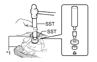
  1. Using SST and a wooden block, tap in a new oil pump seal until its surface is flush with the timing chain cover edge.
    Text in Illustration 
    *1
    Wooden Block

    SST
    09550-60010   (09951-00250, 09951-00380, 09952-06010)
    09950-70010  

    Tap in depth:
    0 to 1.0 mm from the edge of the timing chain cover.

    NOTICE:
    Do not tap the oil pump seal at an angle.


2. INSTALL TIMING CHAIN COVER
  1. Install 2 new O-rings to the cylinder block and oil pan.


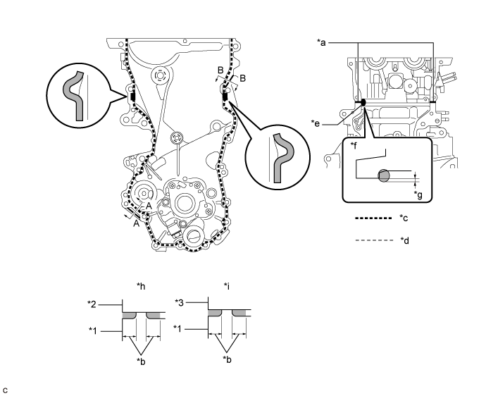
  1. Apply seal packing to the timing chain cover and engine assembly as shown in the illustration below.


    A314945E01


    Text in Illustration 
    *1
    Timing Chain Cover
    *2
    Cylinder Block
    *3
    Cylinder Head Sub-assembly
    -
    -
    *a
    Apply Seal Packing to The Inner Corners
    *b
    2.5 mm (0.0984 in.) or Higher
    *c
    Seal Packing Application Width 3.5 to 4.5 mm (0.138 to 0.177 in.)
    *d
    Seal Packing Application Width 1.5 to 2.0 mm (0.0591 to 0.0787 in.)
    *e
    Seal Packing Application Width 10 mm (0.394 in.) or more
    *f
    Upper View
    *g
    Apply enough seal packing so that it will protrude beyond the timing chain cover installation surface
    *h
    A - A (After Installation)
    *i
    B - B (After Installation)
    -
    -

    Seal packing:
    Toyota Genuine Seal Packing Black, Three Bond 1207B or equivalent

    NOTICE:
    1. When the contact surfaces are wet, clean the surfaces with non-residue solvent before applying seal packing.
    2. Install the timing chain cover within 3 minutes and tighten the bolts within 10 minutes of applying seal packing.
    3. Do not apply engine oil for at least 2 hours after installation.


    A265763E01
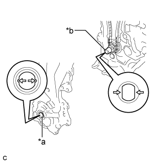
  1. Align the oil pump drive rotor spline and the crankshaft as shown in the illustration.
    Text in Illustration 
    *a
    Drive Rotor Spline
    *b
    Crankshaft


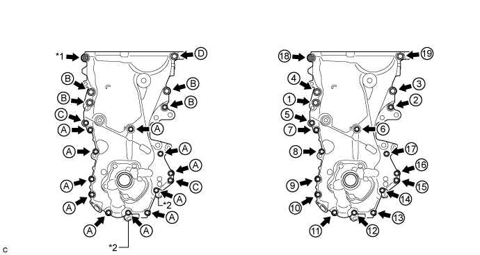
  1. Temporarily install the timing chain cover and 2 wire harness clamp brackets with the 18 bolts and nut.


    A267064E01


    Text in Illustration 
    *1
    Nut
    *2
    Wire Harness Clamp Bracket
    Bolt Length 
    Item
    Length
    Thread Diameter
    Bolt A
    20 mm (0.787 in.)
    6 mm (0.236 in.)
    Bolt B
    30 mm (1.18 in.)
    8 mm (0.315 in.)
    Bolt C
    35 mm (1.38 in.)
    6 mm (0.236 in.)
    Bolt D
    20 mm (0.787 in.)
    8 mm (0.315 in.)

    NOTICE:
    1. Be careful not to disturb the seal packing.
    2. After installing the timing chain cover, install the engine mounting bracket RH within 10 minutes.

  1. Tighten the 18 bolts and nut in the sequence shown in the illustration.

    Torque:
    Bolt A and Bolt C:
    12 N*m{ 122 kgf*cm , 9 ft.*lbf }
    Bolt B:
    32 N*m{ 326 kgf*cm , 24 ft.*lbf }
    Bolt D and Nut:
    24 N*m{ 245 kgf*cm , 18 ft.*lbf }


3. INSTALL SCREW PLUG
  1. Apply a few drops of adhesive to 2 or 3 threads of the screw plug.

    Adhesive:
    Toyota Genuine Adhesive 1324, Three Bond 1324 or equivalent

  1. Using an 8 mm hexagon socket wrench, install the screw plug.

    Torque:
    15 N*m{ 153 kgf*cm , 11 ft.*lbf }


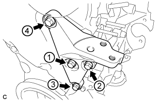
4. INSTALL ENGINE MOUNTING BRACKET RH
  1. Temporarily install the engine mounting bracket RH with the 4 bolts.


    A266946E01
  1. Tighten the 4 bolts in the sequence shown in the illustration.

    Torque:
    55 N*m{ 561 kgf*cm , 41 ft.*lbf }


5. INSTALL ENGINE OIL LEVEL DIPSTICK GUIDE
  1. Apply a light coat of engine oil to a new O-ring and install the O-ring to the engine oil level dipstick guide.

  1. Install the engine oil level dipstick guide with the bolt.

    Torque:
    10 N*m{ 102 kgf*cm , 7 ft.*lbf }


6. INSTALL ENGINE OIL LEVEL DIPSTICK
  1. Install the engine oil level dipstick.


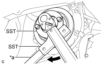
7. INSTALL CRANKSHAFT DAMPER SUB-ASSEMBLY
  1. Align the hole of the crankshaft damper sub-assembly with the straight pin, then install the crankshaft damper sub-assembly.


    A266941E01
  1. Using SST, hold the crankshaft damper sub-assembly in place and tighten the bolt.
    Text in Illustration 
    *a
    Hold
    V100135
    Turn

    SST
    09213-58012   (91111-50845)
    09330-00021  

    Torque:
    128 N*m{ 1305 kgf*cm , 94 ft.*lbf }

    NOTICE:
    When installing SST, be careful that the bolt which holds SST does not interfere with the timing chain cover.


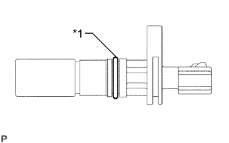
8. INSTALL CRANKSHAFT POSITION SENSOR


    A087546E02
  1. Apply a light coat of engine oil to the O-ring on the crank position sensor.
    Text in Illustration 
    *1
    O-ring

  1. Install the crank position sensor with the bolt.

    Torque:
    7.5 N*m{ 76 kgf*cm , 66 in.*lbf }

    Connect the crank position sensor connector.


9. INSTALL CYLINDER HEAD COVER SUB-ASSEMBLY
  1. Install a new gasket to the cylinder head cover sub-assembly.


    A267067
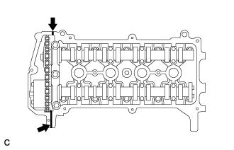
  1. Apply seal packing to the 2 locations shown in the illustration.
    Text in Illustration 
    V100135
    Apply Seal Packing

    Seal packing:
    Toyota Genuine Seal Packing Black, Three Bond 1207B or equivalent

    NOTICE:
    1. Remove any oil from the contact surface.
    2. Install the cylinder head cover within 3 minutes of applying seal packing.
    3. Do not start the engine for at least 2 hours after installation.


    A265764E01
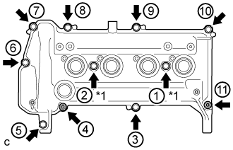
  1. Temporarily install the cylinder head cover sub-assembly with the 9 bolts, 2 nuts and 2 new seal washers.
    Text in Illustration 
    *1
    Seal Washer

  1. Using several steps, uniformly tighten the bolts and nuts in the sequence shown in the illustration.

    Torque:
    13 N*m{ 132 kgf*cm , 10 ft.*lbf }

  1. Connect the No. 1 ventilation hose and No. 2 ventilation hose.


10. CONNECT ENGINE WIRE (for LHD)
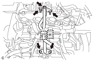
  1. Install the engine wire with the 3 bolts.

    Torque:
    8.4 N*m{ 85 kgf*cm , 74 in.*lbf }

  1. Connect the wire harness clamp.

  1. Connect the 4 injector connectors.


11. CONNECT ENGINE WIRE (for RHD)
  1. Install the engine wire with the 3 bolts.

    Torque:
    8.4 N*m{ 85 kgf*cm , 74 in.*lbf }

  1. Connect the 4 injector connectors.


12. INSTALL IGNITION COIL ASSEMBLY


    A268161E01
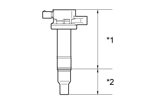
  1. Install the 4 No. 1 ignition coils with the 4 bolts.
    Text in Illustration 
    *a
    Body
    *b
    Cap

    Torque:
    10 N*m{ 102 kgf*cm , 7 ft.*lbf }

    NOTICE:
    If the body or cap of the No. 1 ignition coil is dropped or subjected to a strong impact, replace the No. 1 ignition coil with a new one.

    HINT:
    Perform "Inspection After Repairs" after replacing the ignition coil assembly (Click here).

  1. Connect the 4 No. 1 ignition coil connectors.


13. INSTALL EGR VALVE WITH COOLER ASSEMBLY
  1. Using an E8 "TORX" socket wrench, install the 2 stud bolts.

    Torque:
    9.0 N*m{ 92 kgf*cm , 80 in.*lbf }

  1. Install a new gasket and the EGR valve assembly with the 2 bolts.

    Torque:
    25 N*m{ 255 kgf*cm , 18 ft.*lbf }

  1. Connect the No. 1 water by-pass hose.

  1. Temporarily install a new gasket and the EGR valve with cooler assembly with the 2 bolts and 2 nuts.

  1. Install the EGR valve bracket with the 2 bolts and nut.

    Torque:
    25 N*m{ 255 kgf*cm , 18 ft.*lbf }

  1. Install the EGR valve with cooler assembly with the 2 bolts and 2 nuts.

    Torque:
    25 N*m{ 255 kgf*cm , 18 ft.*lbf }

    NOTICE:
    Make sure that all installation surfaces of the EGR valve with cooler assembly are in even contact when tightening the bolts and nuts.


    A275468E01
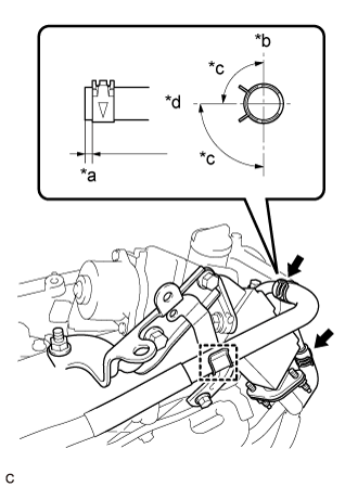
  1. Connect the No. 4 water by-pass hose and No. 5 water by-pass hose.
    Text in Illustration 
    *a
    2 to 7 mm (0.079 to 0.276 in.)
    *b
    Up
    *c
    90°
    *d
    Engine Rear

  1. Install the wire harness clamp bracket with the bolt.

    Torque:
    13 N*m{ 127 kgf*cm , 9 ft.*lbf }


    A267673
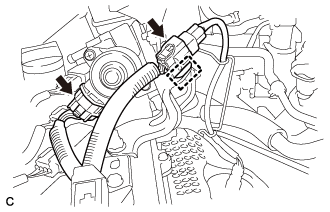
  1. Connect the 2 connectors and wire harness clamp.


14. INSTALL NO. 2 EGR PIPE


    A268229
  1. Install 2 new gaskets and the No. 2 EGR pipe with the 2 bolts and 2 nuts.

    Torque:
    Bolt:
    10 N*m{ 102 kgf*cm , 7 ft.*lbf }
    Nut:
    25 N*m{ 255 kgf*cm , 18 ft.*lbf }

    NOTICE:
    Make sure to tighten the 4 bolts evenly until the flanges of the EGR pipe assembly contact the installation surfaces.

  1. Connect the clamp and No. 2 water by-pass hose.

  1. Connect the wire harness clamp.


15. REMOVE ENGINE STAND
(Click here)