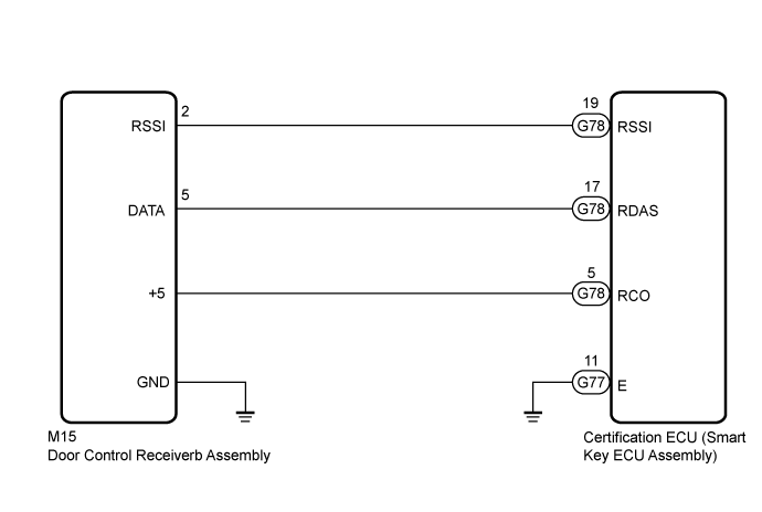
DTC B1242 Wireless Door Lock Tuner Circuit Malfunction |
| DTC No. | DTC Detection Condition | Trouble Area |
| B1242 |
|
|
| For 5 Pin Type |
| For 12 Pin Type |
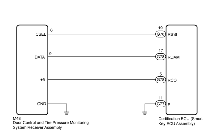
| 1.CHECK CERTIFICATION ECU (SMART KEY ECU ASSEMBLY) |
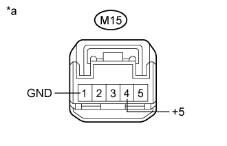 |
For 5 Pin Type
Disconnect the M15 door control receiver connector.
Measure the resistance and voltage according to the value(s) in the table below.
| Tester Connection | Condition | Specified Condition |
| M15-4 (+5) - M15-1 (GND) | Procedure:
| Below 1 V → 4.5 to 5.5 V |
| M15-5 (DATA) - M15-1 (GND) | Procedure:
| Pulse generation |
| M15-2 (RSSI) - M15-1 (GND) | Procedure:
| 11 to 14 V → Below 2 V |
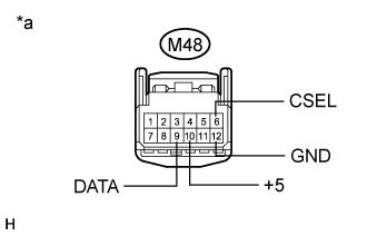 |
For 12 Pin Type
Disconnect the M48 door control receiver connector.
Measure the resistance and voltage according to the value(s) in the table below.
| Tester Connection | Condition | Specified Condition |
| M48-10 (+5) - M48-12 (GND) | Procedure:
| Below 1 V → 4.5 to 5.5 V |
| M48-9 (DATA) - M48-12 (GND) | Procedure:
| Below 1V → 10 to 16 V → Below 1V |
| M48-6 (CSEL) - M48-12 (GND) | Procedure:
| No pulse generation → Pulse generation |
| Tester Connection | Condition | Specified Condition |
| M48-12 (GND) - Body ground | Always | Below 1 Ω |
| *a | Front view of wire harness connector (to Door Control Receiver) |
| Result | Proceed to |
| OK | A |
| OK (for 5 Pin Type) | B |
| OK (for 12 Pin Type) | C |
|
| ||||
|
| ||||
| A | |
 |
| 2.CHECK HARNESS AND CONNECTOR (DOOR CONTROL RECEIVER - CERTIFICATION ECU (SMART KEY ECU ASSEMBLY)) |
For 5 Pin Type
Disconnect the G77 and G78 certification ECU (smart key ECU assembly) connectors.
Measure the resistance according to the value(s) in the table below.
| Tester Connection | Condition | Specified Condition |
| G78-19 (RSSI) - M15-2 (RSSI) | Always | Below 1 Ω |
| G78-17 (RDAS) - M15-5 (DATA) | Always | Below 1 Ω |
| G78-5 (RCO) - M15-4 (+5) | Always | Below 1 Ω |
| G77-11 (E) - Body ground | Always | Below 1 Ω |
| M15-1 (GND) - Body ground | Always | Below 1 Ω |
| G78-19 (RSSI) or M15-2 (RSSI) - Body ground | Always | 10 kΩ or higher |
| G78-17 (RDAS) or M15-5 (DATA) - Body ground | Always | 10 kΩ or higher |
| G78-5 (RCO) or M15-4 (+5) - Body ground | Always | 10 kΩ or higher |
For 12 Pin Type
Disconnect the G77 and G78 certification ECU (smart key ECU assembly) connectors.
Measure the resistance according to the value(s) in the table below.
| Tester Connection | Condition | Specified Condition |
| G78-19 (RSSI) - M48-6 (CSEL) | Always | Below 1 Ω |
| G78-17 (RDAM) - M48-9 (DATA) | Always | Below 1 Ω |
| G78-5 (RCO) - M48-10 (+5) | Always | Below 1 Ω |
| G77-11 (E) - Body ground | Always | Below 1 Ω |
| M48-12 (GND) - Body ground | Always | Below 1 Ω |
| G78-19 (RSSI) or M48-6 (CSEL) - Body ground | Always | 10 kΩ or higher |
| G78-17 (RDAM) or M48-9 (DATA) - Body ground | Always | 10 kΩ or higher |
| G78-5 (RCO) or M48-10 (+5) - Body ground | Always | 10 kΩ or higher |
|
| ||||
| OK | ||
 | ||
| ||
