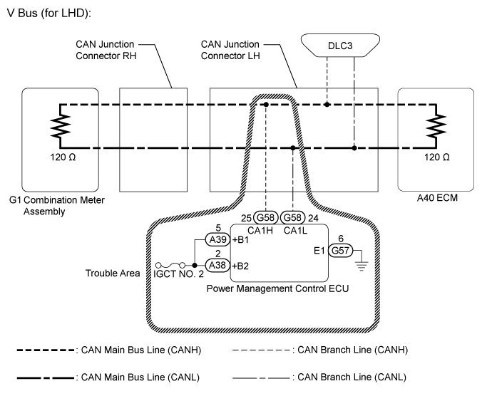
CAN COMMUNICATION SYSTEM > Power Management Control ECU Communication Stop Mode |
| Detection Item | Symptom | Trouble Area |
| Power Management Control ECU Communication Stop Mode |
|
|
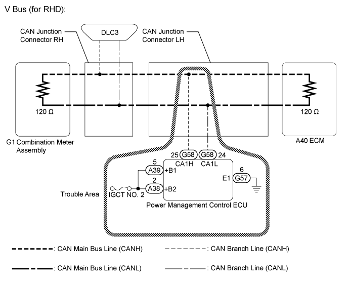
| 1.CHECK FOR OPEN IN CAN BUS LINES (POWER MANAGEMENT CONTROL ECU BRANCH LINE) |
Disconnect the cable from the negative (-) auxiliary battery terminal.
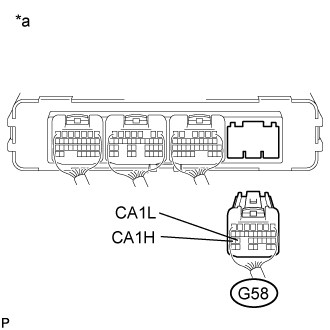 |
Disconnect the power management control ECU connector.
Measure the resistance according to the value(s) in the table below.
| Tester Connection | Condition | Specified Value |
| G58-25 (CA1H) - G58-24 (CA1L) | Cable disconnected from negative (-) auxiliary battery terminal | 54 to 69 Ω |
| *a | Rear view of wire harness connector (to Power Management Control ECU) |
|
| ||||
| OK | |
 |
| 2.CHECK HARNESS AND CONNECTOR (GROUND TERMINAL) |
Reconnect the (G58) power management control ECU connector.
Disconnect the (G57) power management control ECU connector.
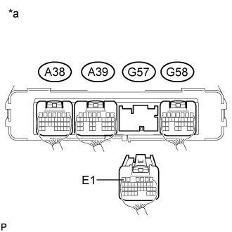 |
Measure the resistance according to the value(s) in the table below.
| Tester Connection | Condition | Specified Value |
| G57-6 (E1) - Body ground | Cable disconnected from negative (-) auxiliary battery terminal | Below 1 Ω |
| *a | Rear view of wire harness connector (to Power Management Control ECU) |
|
| ||||
| OK | |
|
| 3.CHECK HARNESS AND CONNECTOR (POWER SOURCE TERMINAL) |
Reconnect the (G57) power management control ECU connector.
Connect the cable to the negative (-) auxiliary battery terminal.
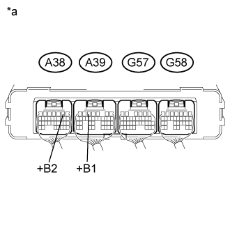 |
Measure the voltage according to the value(s) in the table below.
| Tester Connection | Switch Condition | Specified Value |
| A39-5 (+B1) - Body ground | Power switch on (IG) | 11 to 14 V |
| A38-2 (+B2) - Body ground | Power switch on (IG) | 11 to 14 V |
| *a | Component with harness connected (Power Management Control ECU) |
|
| ||||
| OK | ||
 | ||
| ||
