 |
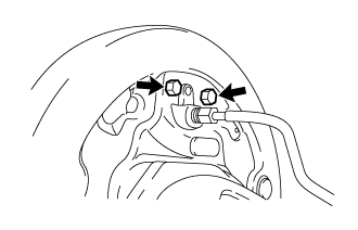
Install the rear wheel brake cylinder assembly to the backing plate with the 2 bolts.
- Torque:
- 9.8 N*m{ 100 kgf*cm , 87 in.*lbf }
REAR BRAKE > INSTALLATION |
| 1. INSTALL REAR WHEEL BRAKE CYLINDER ASSEMBLY |
|
Install the rear wheel brake cylinder assembly to the backing plate with the 2 bolts.
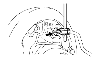 |
Using a union nut wrench, connect the brake line to the rear wheel brake cylinder assembly.
| 2. TEMPORARILY TIGHTEN REAR DRUM BRAKE BLEEDER PLUG |
| 3. INSTALL REAR DRUM BRAKE BLEEDER PLUG CAP |
| 4. INSTALL REAR BRAKE AUTOMATIC ADJUST LEVER |
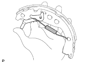 |
Install the rear brake automatic adjust lever and automatic adjust lever tension spring to the rear brake shoe (front).
| 5. CONNECT NO. 3 PARKING BRAKE CABLE ASSEMBLY |
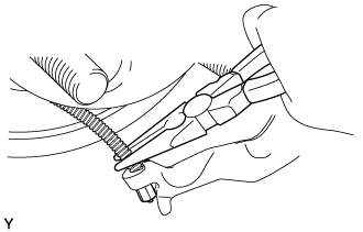 |
Using needle-nose pliers, install the No. 3 parking brake cable assembly to the rear brake parking brake shoe lever sub-assembly.
| 6. INSTALL REAR BRAKE STRUT KIT |
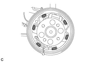 |
Apply high temperature grease to the surface of the backing plate that contacts the shoes as shown in the illustration.
 | High Temperature Grease |
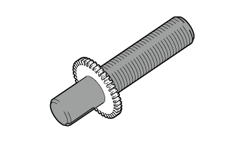 |
Apply high temperature grease to the adjustment bolt.
| High Temperature Grease |
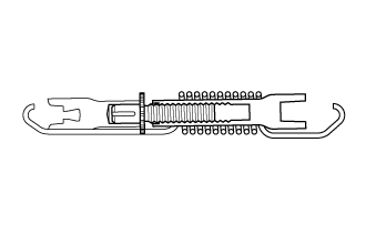 |
Assemble the rear brake strut kit as shown in the illustration.
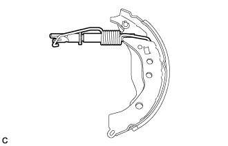 |
Install the rear brake strut kit to the rear brake shoe.
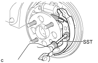 |
Using SST, install the rear brake shoe, shoe hold down spring pin, shoe hold down spring and shoe hold down spring cup.
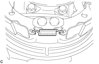 |
Install the shoe tension spring to the rear brake shoe.
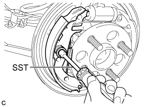 |
Using SST, install the rear brake shoe, shoe hold down spring pin, shoe hold down spring and shoe hold down spring cup.
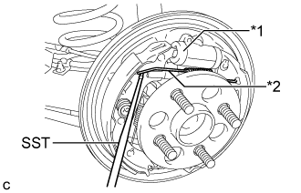 |
Using SST, install the tension spring to the rear brake shoe.
| *1 | Wheel Cylinder Boot |
| *2 | Tension Spring |
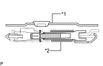 |
Inspect the rear brake strut set is installed properly as shown in the illustration.
| *1 | Back Plate |
| *2 | Rear Brake Strut Set |
| 7. INSPECT REAR DRUM BRAKE |
Inspect that each part is installed properly as shown in the illustration.
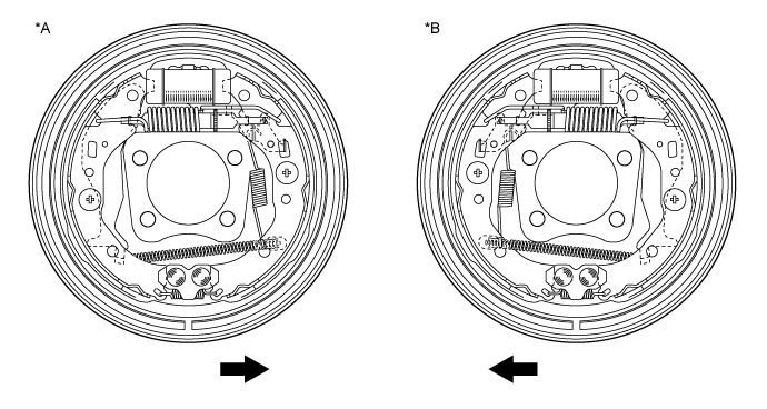
| *A | RH Side | *B | LH Side |
 | Front of the Vehicle | - | - |
| 8. INSTALL REAR BRAKE DRUM SUB-ASSEMBLY |
Install the rear brake drum.
| 9. ADJUST REAR DRUM BRAKE SHOE CLEARANCE |
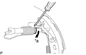 |
Temporarily install the 2 wheel nuts.
| Expand |
Remove the shoe adjusting hole plug, and turn the adjuster to expand the shoe until the drum locks.
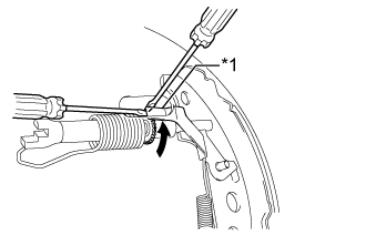 |
Hold the automatic adjust lever away from the adjuster, and contract the brake shoe by turning the adjust bolt using another screwdriver until the drum can rotate smoothly.
| *1 | Automatic Adjust Lever |
| Contract |
Install the hole plug.
| 10. CONNECT CABLE TO NEGATIVE AUXILIARY BATTERY TERMINAL |
Connect the cable to the negative (-) auxiliary battery terminal .
Perform the following procedure if air bleeding is not necessary:
Connect the reservoir level switch connector.
Clear the DTCs (Click here).
| 11. BLEED BRAKE LINE |
Separate the center No. 1 cowl top ventilator louver.
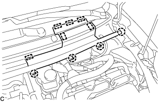 |
for LHD:
Disengage the 4 claws and 6 guides, and separate the center No. 1 cowl top ventilator louver.
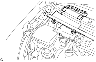 |
for RHD:
Disengage the 3 claws and 5 guides, and separate the center No. 1 cowl top ventilator louver.
Bleed brake line.
Remove the brake master cylinder reservoir filler cap assembly.
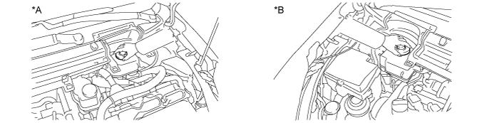
| *A | for LHD | *B | for RHD |
Add brake fluid into the reservoir between the MAX and MIN lines on the brake fluid reservoir.
Connect the intelligent tester to the DLC3 and turn the power switch on (IG).
Turn the intelligent tester on and enter the following menus: Chassis / ABS/VSC/TRC / Air Bleeding.
Select "Usual air bleeding" on the intelligent tester display, and bleed air from the brake fluid following the instructions on the intelligent tester.
After air bleeding, tighten each bleeder plug.
Clear the DTCs (Click here).
Turn the intelligent tester off and turn the power switch off.
Install the brake master cylinder reservoir filler cap.
Inspect for brake fluid leaks.
Install the center No. 1 cowl top ventilator louver.
for LHD:
Engage the 4 claws and 6 guides to install the center No. 1 cowl top ventilator louver.
for RHD:
Engage the 3 claws and 5 guides to install the center No. 1 cowl top ventilator louver.
| 12. ADJUST PARKING BRAKE |
| 13. INSTALL REAR WHEEL |