 |
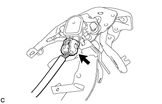
Disconnect the connector from the brake pedal stroke sensor assembly.
BRAKE PEDAL (for LHD) > REMOVAL |
| 1. PRECAUTION |
| 2. ALIGN FRONT WHEELS FACING STRAIGHT AHEAD |
| 3. DISCONNECT CABLE FROM NEGATIVE AUXILIARY BATTERY TERMINAL |
| 4. REMOVE INSTRUMENT CLUSTER FINISH PANEL SUB-ASSEMBLY |
| 5. REMOVE BRAKE PEDAL STROKE SENSOR ASSEMBLY |
|
Disconnect the connector from the brake pedal stroke sensor assembly.
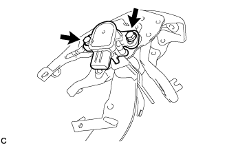 |
Remove the 2 bolts and brake pedal stroke sensor assembly from the brake pedal support assembly.
| 6. REMOVE STOP LIGHT SWITCH ASSEMBLY |
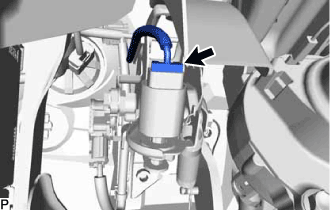 |
Disconnect the connector.
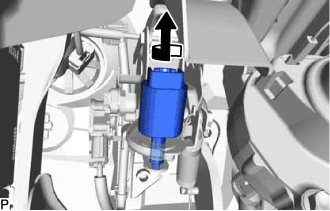 |
Turn the stop light switch assembly counterclockwise and remove it.
| 7. REMOVE STOP LIGHT SWITCH MOUNTING ADJUSTER |
| 8. REMOVE BRAKE PEDAL RETURN SPRING |
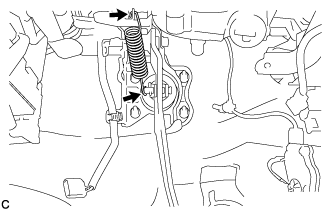 |
Remove the brake pedal return spring from the brake pedal support assembly and push rod pin.
| 9. REMOVE COLUMN HOLE COVER SILENCER SHEET |
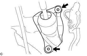 |
Remove the 2 clips and the column hole cover silencer sheet.
| 10. SEPARATE STEERING SLIDING YOKE SUB-ASSEMBLY |
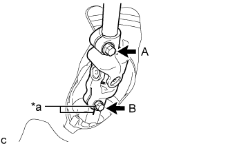 |
Put matchmarks on the steering sliding yoke sub-assembly and steering gear assembly.
| *a | Matchmark |
Loosen bolt A.
Remove bolt B.
Separate the steering sliding yoke sub-assembly from the steering gear assembly.
| 11. REMOVE NO. 2 STEERING INTERMEDIATE SHAFT ASSEMBLY |
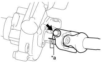 |
Put matchmarks on the No. 2 steering intermediate shaft assembly and steering column assembly.
| *a | Matchmark |
Remove the bolt.
Remove the steering intermediate shaft assembly from the steering column assembly.
| 12. REMOVE PUSH ROD PIN |
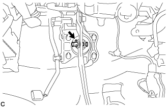 |
Remove the clip and push rod pin to separate the brake pedal support assembly from the push rod clevis.
| 13. REMOVE BRAKE PEDAL SUPPORT ASSEMBLY |
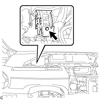 |
Disengage the wire harness clamp from the brake pedal support assembly.
Remove the bolt and separate the brake pedal support assembly from the instrument panel reinforcement assembly.
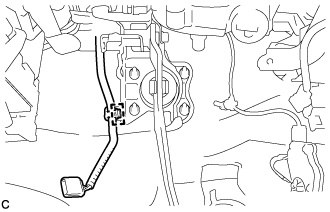 |
Disengage the wire harness clamp from the brake pedal support assembly.
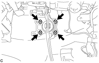 |
Remove the 4 nuts and brake pedal support assembly.