 |
Temporarily install the upper radiator support sub-assembly with the 5 bolts.
CONDENSER > INSTALLATION |
| 1. INSTALL NO. 1 COOLER CONDENSER CUSHION |
Install the 4 No. 1 cooler condenser cushions to the cooler condenser assembly.
| 2. INSTALL COOLER CONDENSER ASSEMBLY |
Engage the 2 guides to install the cooler condenser assembly.
| 3. CONNECT LIQUID PIPE SUB-ASSEMBLY |
Remove the attached vinyl tape from the liquid pipe sub-assembly and the connecting part of the cooler condenser assembly.
Apply sufficient compressor oil to a new O-ring and the fitting surface of the pipe joint.
Install the O-ring onto the liquid pipe sub-assembly.
Install the liquid pipe sub-assembly onto the cooler condenser assembly with the bolt.
| 4. CONNECT NO. 1 COOLER REFRIGERANT DISCHARGE HOSE |
Remove the attached vinyl tape from the No. 1 cooler refrigerant discharge hose and the connecting part of the cooler condenser assembly.
Apply sufficient compressor oil to a new O-ring and the fitting surface of the hose joint.
Install the O-ring onto the No. 1 cooler refrigerant discharge hose.
Install the No. 1 cooler refrigerant discharge hose onto the cooler condenser assembly with the bolt.
| 5. INSTALL NO. 2 FAN SHROUD |
Install the No. 2 fan shroud with the 2 bolts and 2 claws.
| 6. INSTALL UPPER RADIATOR SUPPORT SUB-ASSEMBLY |
Install the 2 radiator support cushions.
|
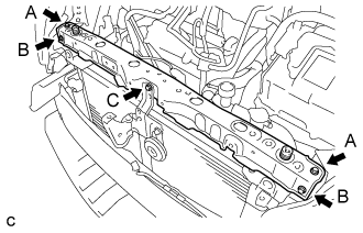
Temporarily install the upper radiator support sub-assembly with the 5 bolts.
Fully tighten the bolt (A).
Fully tighten the bolt (B).
Fully tighten the bolt (C).
Connect the clamp of the hood lock control cable.
Connect the cooling fan ECU connector and 3 clamps.
Connect the horn connector.
| 7. INSTALL HOOD LOCK SUPPORT SUB-ASSEMBLY |
Install the hood lock support sub-assembly with the 2 bolts.
Connect the connector.
| 8. INSTALL HOOD LOCK ASSEMBLY |
Apply MP grease to the sliding areas of the hood lock assembly.
Connect the hood lock control cable.
Install the hood lock with the 3 bolts.
| 9. INSTALL FRONT BUMPER REINFORCEMENT |
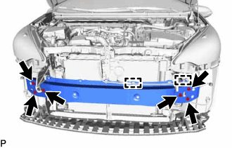 |
Install the front bumper reinforcement with the 6 bolts.
Engage the 2 clamps and install the wire harness.
| 10. INSTALL FRONT BUMPER ENERGY ABSORBER |
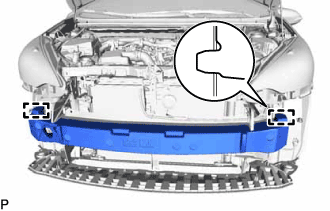 |
Engage the 2 guides to install the front bumper energy absorber.
| 11. INSTALL RADIATOR SUPPORT EXTENSION LH |
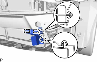 |
Engage the 2 claws and install the radiator support extension LH.
Engage the 2 clamps to install the thermistor assembly.
| 12. INSTALL RADIATOR SUPPORT EXTENSION RH |
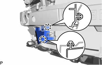 |
Engage the 2 claws and install the radiator support extension RH.
| 13. INSTALL NO. 2 RADIATOR SIDE AIR SEAL |
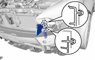 |
Engage the 2 claws and install the No. 2 radiator side air seal.
| 14. INSTALL NO. 1 RADIATOR SIDE AIR SEAL |
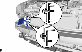 |
Engage the 2 claws and install the No. 1 radiator side air seal.
| 15. INSTALL RADIATOR SUPPORT OPENING COVER |
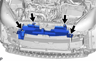 |
Install the radiator support opening cover with the 6 clips.
| 16. INSTALL FRONT BUMPER ASSEMBLY |
| 17. INSPECT HOOD SUB-ASSEMBLY |
Check that the clearance measurements of areas "a" through "f" are within each standard range.
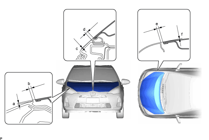
| Area | Measurement | Area | Measurement |
| a | -0.85 to 3.15 mm (-0.0335 to 0.124 in.) | b | 1.65 to 5.65 mm (0.065 to 0.222 in.) |
| c | -1.85 to 2.15 mm (-0.0728 to 0.0847 in.) | d | 2.35 to 6.35 mm (0.0925 to 0.25 in.) |
| e | 2.0 to 5.0 mm (0.0787 to 0.197 in.) | f | -1.5 to 1.5 mm (-0.0591 to 0.0591 in.) |
| 18. ADJUST HOOD SUB-ASSEMBLY |
Horizontally and vertically adjust the hood.
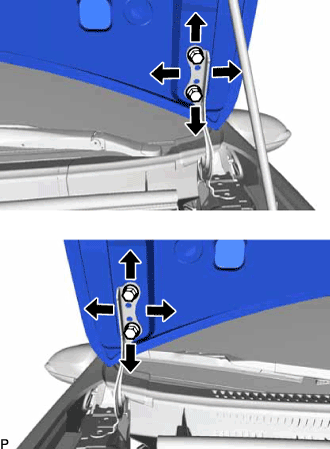 |
Loosen the 4 hinge bolts of the hood.
Adjust the clearance between the hood and front fender by moving the hood.
Tighten the 4 hinge bolts after the adjustment.
Adjust the height of the front end of the hood using the cushion rubbers.
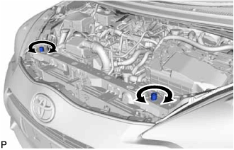 |
Adjust the 2 cushion rubbers so that the heights of the hood and fender are aligned.
Adjust the hood lock.
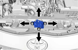 |
Loosen the 3 bolts.
Tighten the bolts after adjustment.
Check that the striker can engage with the hood lock smoothly.
| 19. CHARGE AIR CONDITIONING SYSTEM WITH REFRIGERANT |
Perform vacuum purging using a vacuum pump or appropriate equipment.
Charge the air conditioning system with refrigerant.
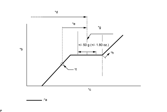
| *a | Sub-cool System | *b | High Pressure |
| *c | Refrigerant Amount | *d | Standard charge amount |
| *e | Charge additional 100g (3.5 oz.) | *f | Point where bubbles disappear |
| *g | Mean value in proper range | *h | Overcharged |
| 20. WARM UP COMPRESSOR |
Keep the A/C switch on for at least 2 minutes to warm up the compressor.
| 21. INSPECT FOR REFRIGERANT LEAK |
After recharging the air conditioning system with refrigerant, inspect for refrigerant leaks using a halogen leak detector.
Carry out the test under the following conditions:
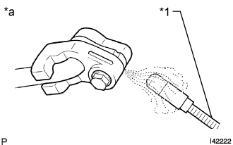 |
Using a halogen leak detector, inspect for refrigerant leaks from the air conditioning system.
| *1 | Halogen Leak Detector |
| *a | Inspect for Leak |
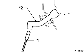 |
Bring the halogen leak detector close to the drain hose with the detector power off, and then turn the detector on.
| *1 | Halogen Leak Detector |
| *2 | Drain Hose |
If a refrigerant leak is not detected from the drain hose, remove the blower motor control from the cooling unit. Insert the halogen leak detector sensor into the unit and check for a leak.
Disconnect the pressure sensor connector and leave it for approximately 20 minutes. Bring the halogen leak detector close to the pressure sensor and check for a leak.